8 Rittal Blue e+ fan-and-filter unit assembly and operating instructions
EN
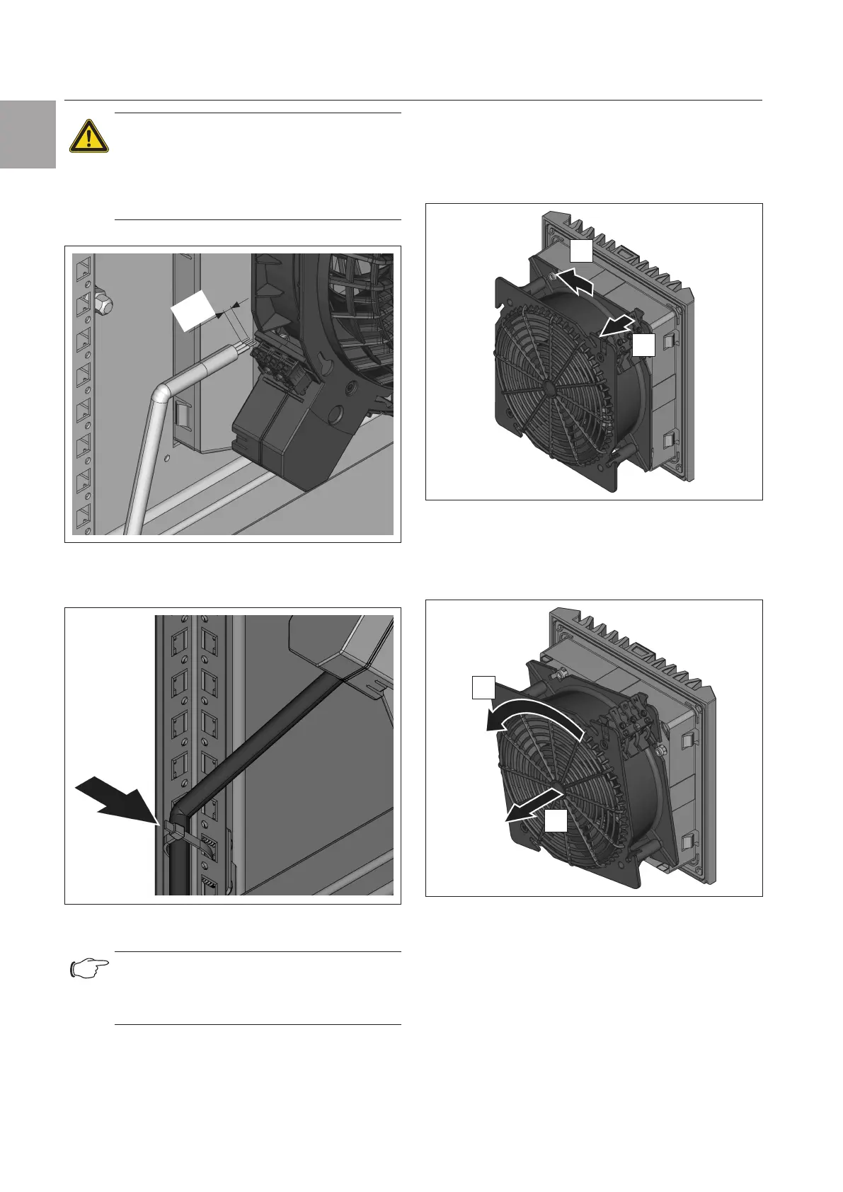
Carrying out the electrical connection
Caution!
If no wire end ferrules are used, the
insulation of the individual wires should
be stripped to a max. of 9mm (to
comply with clearance and creepage
distances).
max.
9 mm
Fig.5: Maximum permissible insulation stripping
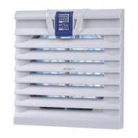
◾ Fasten the connection cable at an appropriate loca-
tion, e.g. the enclosure frame.
Fig.6: Cable fastening with cable ties on the enclosure frame
(example)
Note:
Fan-and-filter unit 3237.xxx is connected by
way of two single wires which are led out of
the unit.
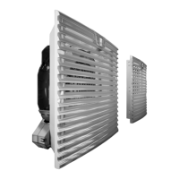
5.2 Rotating the voltage connection
If the position of the voltage connection is not ideally
accessible, it may be rotated through 90° and snapped
into position.
Units 3238.xxx to 3239.xxx
◾ To unlock the bayonet connection, pull the bracket
(see fig.7) of the bayonet catch at the rear of the fan.
This is located on the corner of the connection termi-
nal.
1.
2.
Fig.7: Release the bayonet connection
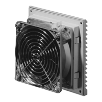
◾ Turn the fan housing counter-clockwise to release the
bayonet connection.
◾ Pull the fan housing backwards away from the filter
box.
3.
4.
Fig.8: Turning the fan housing
◾ Then turn the fan housing by 90°, 180° or 270° so
that the electrical connection is in the desired posi-
tion (see fig.8).
◾ Place the fan housing back on the filter box (see
fig.9).