4 Rittal Blue e+ fan-and-filter unit assembly and operating instructions
EN
Notes on documentation
1 Notes on documentation
These assembly and operating instructions are aimed
at
– tradespersons who are familiar with assembly and
installation of the fan-and-filter unit.
– trained specialists who are familiar with operation of
the fan-and-filter unit.
1.1 Other applicable documents
Paper copies of the assembly and operating instruc-
tions are available for the unit types described here and
are enclosed with the equipment.
We cannot accept any liability for damage associated
with failure to observe these instructions. Where appli-
cable, the instructions for any accessories used also
apply.
1.2 Storing the documents
The assembly and operating instructions as well as all
other applicable documents are an integral part of the
product. They must be given to the plant operator. The
operator is responsible for storage of the documents so
they are readily available when needed.
1.3 Symbols used in these operating in-
structions
Danger!
A dangerous situation in which failure
to comply with the instructions will
result in death or severe injury.
Warning!
A dangerous situation which may cause
death or serious injury if the instruc-
tions are not followed.
Caution!
A dangerous situation which may lead
to (minor) injuries if the instructions are
not followed.
Note:
Important notices and indication of situa-
tions which may result in material damage.
◾ This symbol indicates an "action point" and shows
that you should perform an operation or procedure.
2 Safety instructions
Please observe the following safety instructions when
assembling and operating the unit:
– Always wear the prescribed personal protective
equipment when working on the fan-and-filter unit.
– Do not make any changes to the fan-and-filter unit
other than those described in these and other appli-
cable instructions.
– Carefully debur the mounting cut-out before inserting
the fan-and-filter unit.
– The fan-and-filter unit should be fitted with the mem-
branes in a vertical position.
– The following work must only be carried out by quali-
fied experts or trained personnel and with the system
de-energised:
– Assembly
– Electrical connection
– Changing the direction of airflow
– Changing the mains connection position
– Cleaning
– Maintenance
– Dismantling the fan-and-filter unit
– Connect the pre-fuse specified on the rating plate.
– Strip a maximum of 9mm of the insulation from the
individual wires in the electrical infeed and ensure
that the cables are suitably secured.
– Never insert your fingers into the rotating fan blade.
– Never use flammable cleaning materials.
– Do not obstruct the air inlet and outlet of the fan-
and-filter unit inside and outside the enclosure (see
also section4.2.2 "Layout of the components in the
enclosure", page6).
– The heat loss of the components installed in the en-
closure must not exceed the specific air throughput
of the fan-and-filter unit.
– Use only original spare parts and accessories.
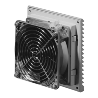
3 Product description
Depending on the model chosen, your fan-and-filter
unit may vary in appearance from the illustrations con-
tained in these instructions. However, the functions are
identical in principle.
1
2
5
4
3
Fig.1: Product description