Rittal Blue e+ fan-and-filter unit assembly and operating instructions 5
EN
Assembly and connections
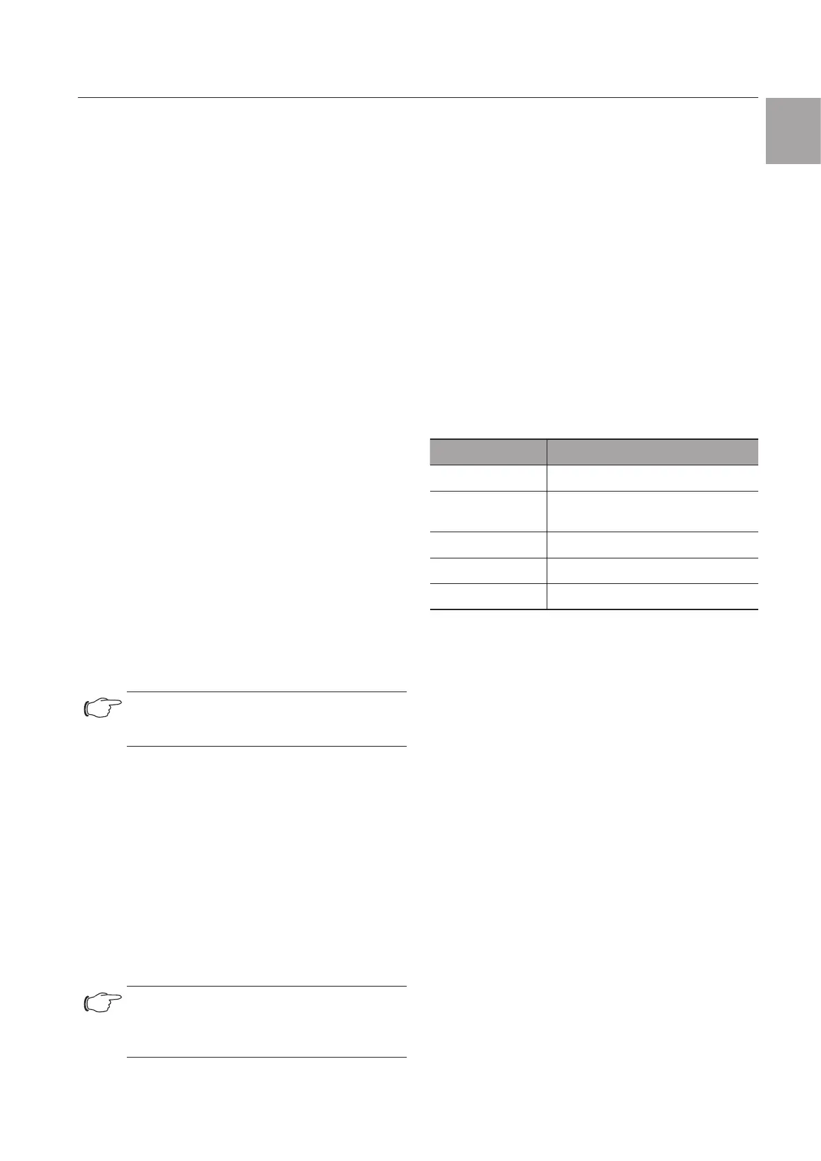
Key
1 Filter box with filter mat
2 Fan housing
3 Variable electrical connection
4 Louvred grille
5 Function logo (to release the louvred grille)
3.1 Functional description
The fan-and-filter unit in conjunction with the corre-
sponding outlet filter(s) is used to dissipate heat loss
from enclosures, ventilate the enclosure and protect
temperature-sensitive components. This is achieved
via the direct infeed of ambient air, the temperature
of which must be less than the admissible enclosure
interior temperature. The system is fitted into prepared
cut-outs.
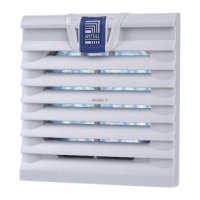
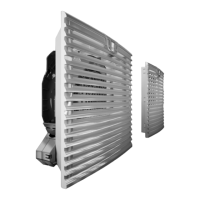
3.1.1 Main components
The fan-and-filter unit is comprised of the following four
main components: Fan motor, filter box, louvred grille
with function logo and filter medium.
3.1.2 Control
We recommend controlling Rittal fan-and-filter units
with one of the following accessories:
– Thermostat (Model No. 3110.000)
– Digital temperature display (Model No. 3114.200)
– Temperature-dependant speed controller (Model No.
3120.200)
– Hygrostat (Model No. 3118.000)
This reduces energy costs, and extends the service
life of the fans and filters. The Rittal fan-and-filter unit
series with EC fans oers the highest energy ecien-
cy as well as a wide range of closed-loop control and
monitoring options.
Note:
Speed controller 3120.200 can be deployed
only for 1-phase AC units.
3.1.3 Safety equipment
The fan is equipped with thermal winding protection
devices for protection against excess current and, in
some cases, against overtemperature. Model 3237.xxx
is impedance-protected. For rotary current fans, the
winding protection is located in the star earthing of the
motor.
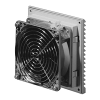
3.1.4 Filter mats
The fan-and-filter unit / outlet filter is supplied with an
installed pleated filter. The filter must be checked regu-
larly in accordance with the level of dust exposure and
replaced as necessary.
Note:
Special filter mats are required for EMC
fan-and-filter units (see section 13 "Acces-
sories").
3.2 Intended use
Rittal fan-and-filter units were developed and designed
in accordance with the state of the art and the recog-
nised rules governing technical safety. Nevertheless, if
used improperly, they may pose a threat to life and limb
or cause damage to property. The unit is only intended
for ventilating enclosures and electronic cases. Any
other use is deemed improper. The manufacturer will
not be liable for any damages caused as a result of
improper use, or for incorrect assembly, installation and
use. All risk is borne solely by the user.
Proper usage also includes the observation of all valid
documents and compliance with the inspection and
servicing conditions.
3.3 Scope of supply
The fan is supplied in a packaging unit in a fully assem-
bled state and ready to connect.
◾ Please check the scope of supply for completeness.
Quantity Description
1 Fan-and-filter unit
4 Mounting screws (not for 3237.7xx
to 3239.7xx)
1 Assembly and operating instructions
1 Drilling template, self-adhesive
1 Pleated filter or EMC filter mat
Tab. 1: Scope of supply
4 Assembly and connections
4.1 Choosing the installation site
When choosing the installation site for the enclosure,
please observe the following:
– The site for the enclosure, and hence the arrange-
ment of the fan-and-filter unit, must be carefully
selected so as to ensure good ventilation.
– The site must be free from excessive dirt and mois-
ture.
– Fan-and-filter units must always be installed on verti-
cal panels (door or walls).
– The ambient temperature must be lower than the
permissible enclosure interior temperature.
– The mains connection data as stated on the rating
plate of the unit must be guaranteed.
4.2 Assembly instructions
4.2.1 General
– Check the packaging carefully for signs of damage.
Any packaging damage may be the cause of a sub-
sequent functional failure.