Rittal Blue e+ fan-and-filter unit assembly and operating instructions 9
EN
Carrying out the electrical connection
5.
6.
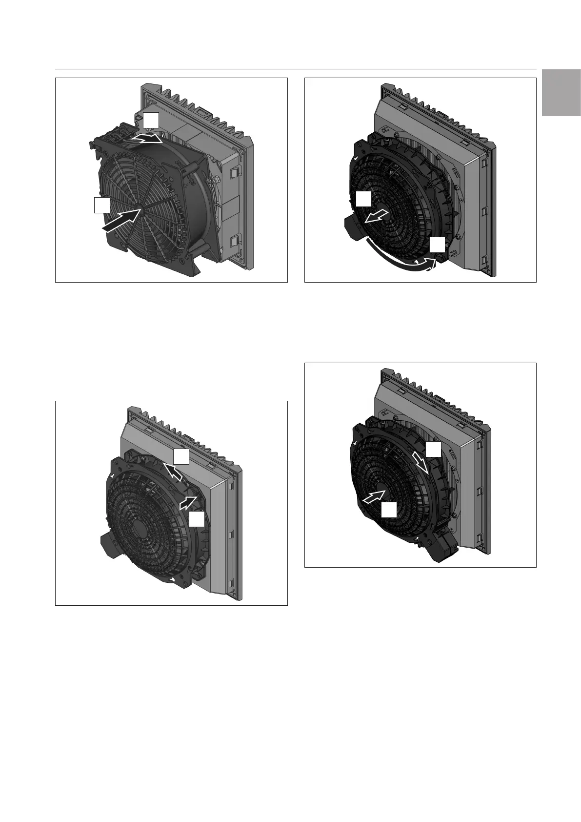
Fig.9: Locking the bayonet connection
◾ Turn the fan housing clockwise until the bayonet
connection latches.
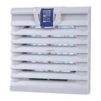
Units 3240.xxx, 3241.xxx, 3243.xxx to 3244.xxx
◾ Press the release button of the bayonet connection
at the rear of the fan (see fig.10).
This is located on the opposite corner from the con-
nection terminal.
1.
2.
Fig.10: Release the bayonet connection
◾ Turn the fan housing counter-clockwise to release the
bayonet connection.
◾ Pull the fan housing backwards away from the filter
box.
3.
4.
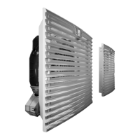
Fig.11: Turning the fan housing
◾ Then turn the fan housing by 90°, 180° or 270° so
that the electrical connection is in the desired posi-
tion (see fig.11).
◾ Place the fan housing back on the filter box (see
fig.12).
5.
6.
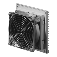
Fig.12: Locking the bayonet connection
◾ Turn the fan housing clockwise until the bayonet
connection latches.
5.3 Changing the direction of airflow
The direction of airflow blows into the enclosure from
the outside as standard.
Should it become necessary to change the direction of
airflow for technical reasons (space, specific compo-
nent air routing etc.), this is easily achieved.
◾ Unlock the bayonet connection and detach the fan
housing from the filter box.
This is done in the same way as described in
section5.2 "Rotating the voltage connection",
page8.
◾ Turn the fan housing by 180°.