Rittal Blue e+ fan-and-filter unit assembly and operating instructions 21
EN
EMC fan/outlet filter
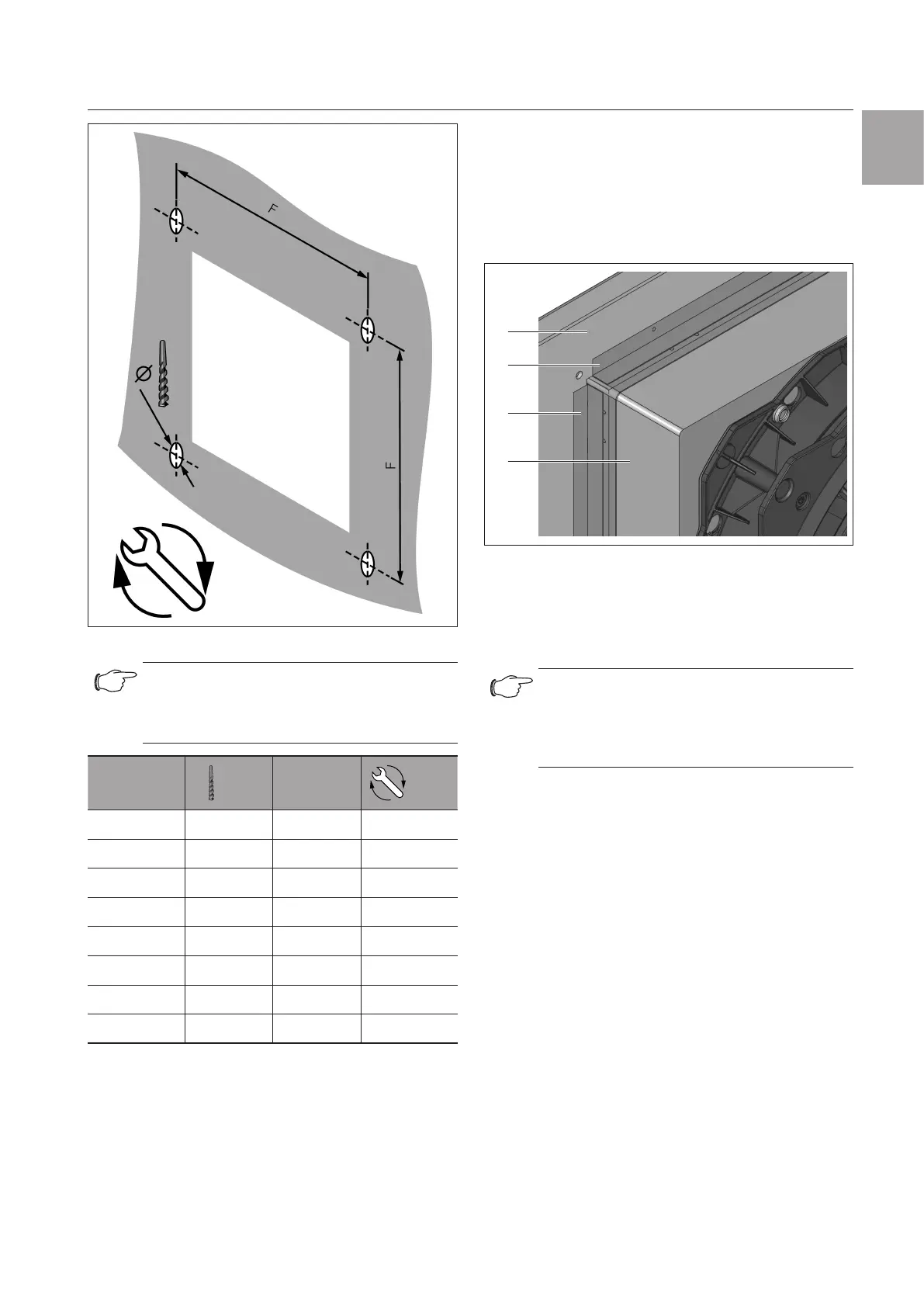
Fig.21: Drilling pattern
Note:
The cut-out must be increased by 1mm
each side for wall thickness above 2.5 mm
(see accompanying drilling template).
Model No.
Ø
mm
F mm
Nm
3237.xxx 3.5 100.5 1
3238.xxx 3.5 132.5 1
3239.xxx 4.5 185 1
3240.xxx 4.5 234 2
3241.xxx 4.5 234 2
3243.xxx 4.5 302 3
3244.xxx 4.5 302 3
3245.xxx 4.5 302 3
Tab. 11: Drilling dimensions
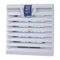
12 EMC fan/outlet filter
To achieve EMC protection, the EMC fans and EMC
outlet filters should be snapped into the mounting cut-
out and screw-fastened using the screws supplied.
Next, the four contact foils should be stuck on allround
between the fan-and-filter unit and the inside of the
enclosure as shown in the following illustration.
1
2
3
2
Fig.22: EMC contact foils
Key
1 Enclosure interior
2 EMC contact foils
3 Fan housing
Note:
EMC protection can only be guaranteed
when using original Rittal EMC filter me-
dia (model nos. 3237.067, 3238.066,
3239.066, 3240.066, 3243.066).