2
IMCD06-E2
2. WIRING
Up to 32 CD101/CD401/CD501/CD701/CD901 digital controller (hereinafter, the "controller")
including the host computer can be connected if multidrop connected by RS-485.
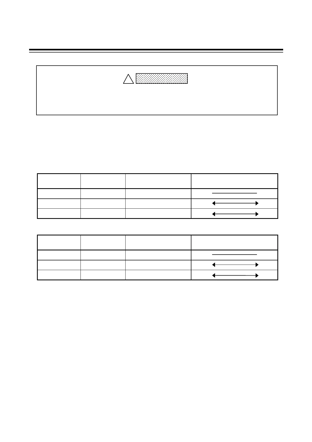
Terminal No. and signal details
CD101/CD401/CD501/CD901
Terminal No.
Signal name
Name
Signal direction
Controller Host computer
13 SG Signal ground
14 T/R(A) Send data/Receive data
15 T/R(B) Send data/Receive data
CD701
Terminal No.
Signal name
Name
Signal direction
Controller Host computer
7 SG Signal ground
8 T/R(A) Send data/Receive data
9 T/R(B) Send data/Receive data
In order to prevent electric shock or instrument failure, do not turn on the power
until all the wiring is finished.
WARNING
!
 Loading...


