201.028 REV 1 Date of Issue: 18 June 2018
Select the Interface, Node Number and Baud Rate as shown, then press ``Use Defaults’’ to assign the ``base
address’’. This will define the start of the block of CAN message identifiers used by the software (using a value
compatible with the J1939 standard).
Press the OK button on the ``Communications Settings’’ and ``Remote Device Settings’’ dialogues. Leave the
Remote Control dialogue open.
Now check that the CMS is now set to automatically perform tests:
− Unplug the CMS circular connector
− Plug it back in
− You should see the connection re-established on the Remote Control dialogue within a few seconds.
− A test should have been automatically started
− The tests should repeat every 10 seconds
− You should see a test result that starts high and decreases with each further test.
Close the Remote Control dialogue and quit the program. Unplug the CMS at the circular connector.
11.2.1.3 PCAN-USB Software
The PCAN-USB adaptor comes with a software CD. This includes a simple CAN-bus diagnostic utility called ``PCAN-
View USB’’. This should be installed from the CD.
Connect the CMS to the computer using the special made-up cable and the PCAN-USB. Power-up the CMS by
turning on the power supply.
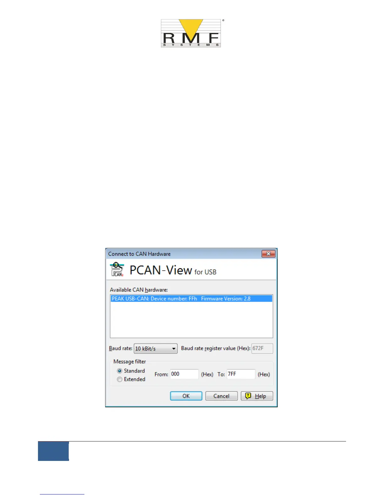
Upon connecting the PCAN-USB and starting PCAN-View, the Connect dialogue is presented.
Figure 11.4 PCAN-View Connect Dialogue
Select a baud rate to match that being used on the CMS, for example 250k. Select the ``Extended’’ message filter
(so that 29 bit identifiers are used). Press OK to go to the main PCAN-View screen.