INSTALLATION
...............................................................................................................................................................................................................
...............................................................................................................................................................................................................
Manual EC 24 · EN05 · 2015-02
9
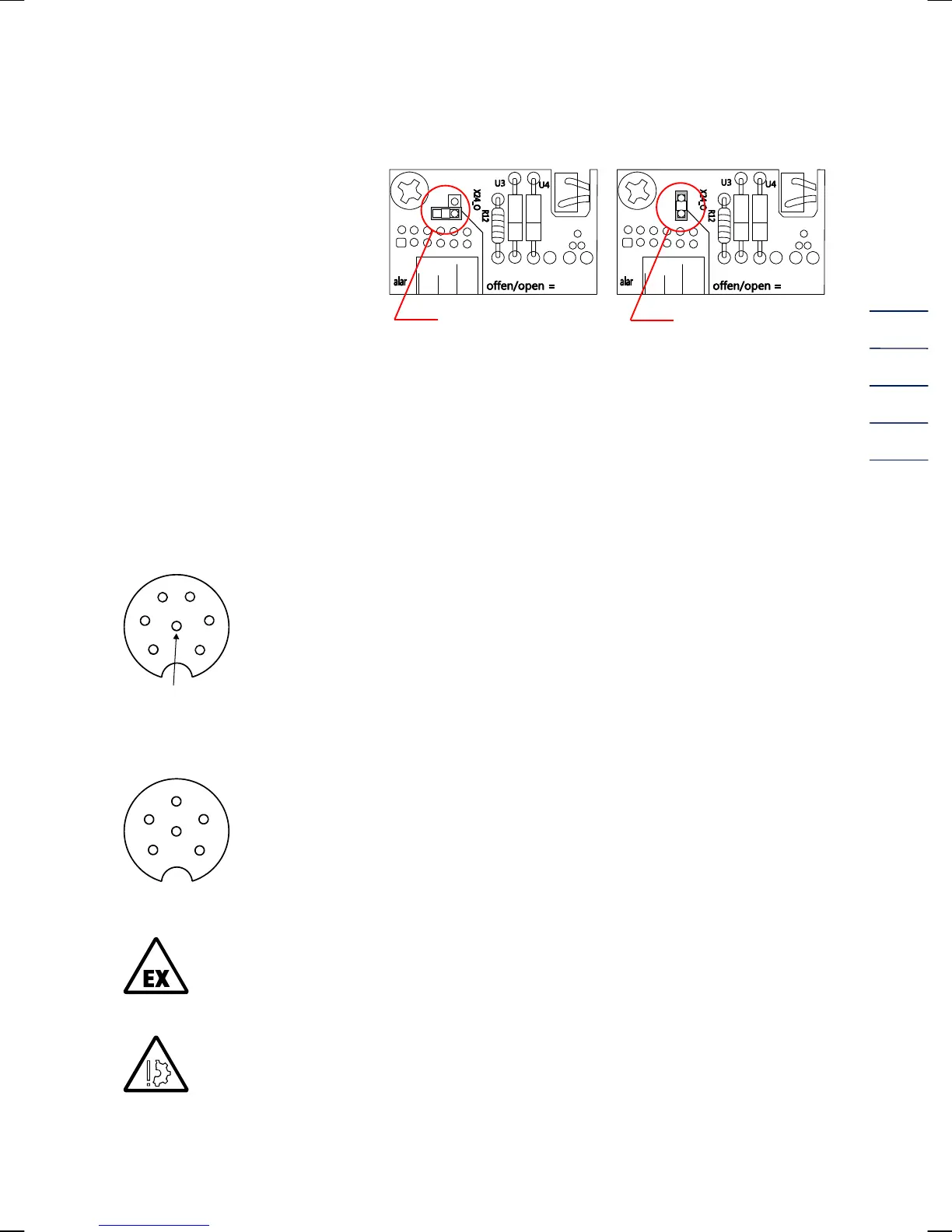
For devices with current output:
Before commissioning, the device
must be activated.
The jumper must be plugged as
shown in the drawing.
deactivated activated
In the case of the EC 21 / EC 24, terminal X22 (on TERZ94trm current module which is plugged in
the main card) is used as current-loop connection to supply the device and as output current (4-
20 mA).
To connect cables to the spring terminals, you need a screwdriver with a blade width of a maximum
of 2.5 mm. Introduce the blade into the intended slot and press down the screwdriver to open the
spring terminal.
Standard connection pulse outputs: 7-pin connector (Binder series 692)
1 - / 4 + LF signal (Vm or Vb)
2 - / 5 + Fault
3 - / 6 + HF signal
(view on device)
Standard connection interface: 7-pin connector (Binder series 423)
1 - / 4 + RS485 supply
3 - / 5 + RS485 data line
2, 6 Spare
(view on device)
In areas subject to explosion hazards, the EC 21 / EC 24 must only be connected to
certified intrinsically safe circuits.
Make sure that the limit values specified in the certificate of conformity (see annex) for
the devices to be connected are not exceeded.
The maximum voltage which may be connected to the RS 485 interface is 10.5 V. A
higher voltage causes damage of the device.
6
5
4
3
2
PE (screening)
1
5
4
6
3
2
1