Do you have a question about the RMG EC 24 and is the answer not in the manual?
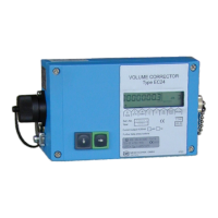
Overview of EC 21/EC 24 correctors, device variants, and system architecture.
Procedure and consequences of resetting the device parameters and meter readings.
Steps to reboot the device, noting potential data loss and required actions.
Operation and estimated battery life for standalone battery-powered units.
Operation via current loop and functionality of standby battery options.
Critical safety precautions, explosion protection standards, and operating temperature limits.
Specific guidelines for installation personnel in hazardous areas, including ATEX compliance.
Details on wiring, terminal blocks, and connectors for proper device setup.
Instructions for connecting an external totalizer unit to the main meter unit.
Description of the device's front panel layout, buttons, and their operational functions.
Explanation of displayed values, pointer positions, energy-saving mode, and wake-up procedures.
Methods for device configuration using internal keys or an external programming module.
Detailed explanation of individual device parameters and their respective operational modes.
Explanation of how the coordinate system facilitates access to device data, configuration, and settings.
Comprehensive list of error codes, hexadecimal values, and their meanings for troubleshooting.
Step-by-step guide for safely replacing the device's internal batteries.
List of symbols, units, and designations for relevant calculation formulas and equations.
Schematic illustrating device inputs, outputs, correction, and signal flow.
Technical data including temperature ranges, device types, input/output capabilities, and supply options.
Wiring diagrams demonstrating connections for battery-powered and mains-powered device configurations.
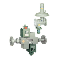
Physical dimensions, flange data, and standard installation orientation for the EC24 unit.
| Brand | RMG |
|---|---|
| Model | EC 24 |
| Category | Controller |
| Language | English |