OPERATION
...............................................................................................................................................................................................................
...............................................................................................................................................................................................................
Manual EC 24 · EN05 · 2015-02
21
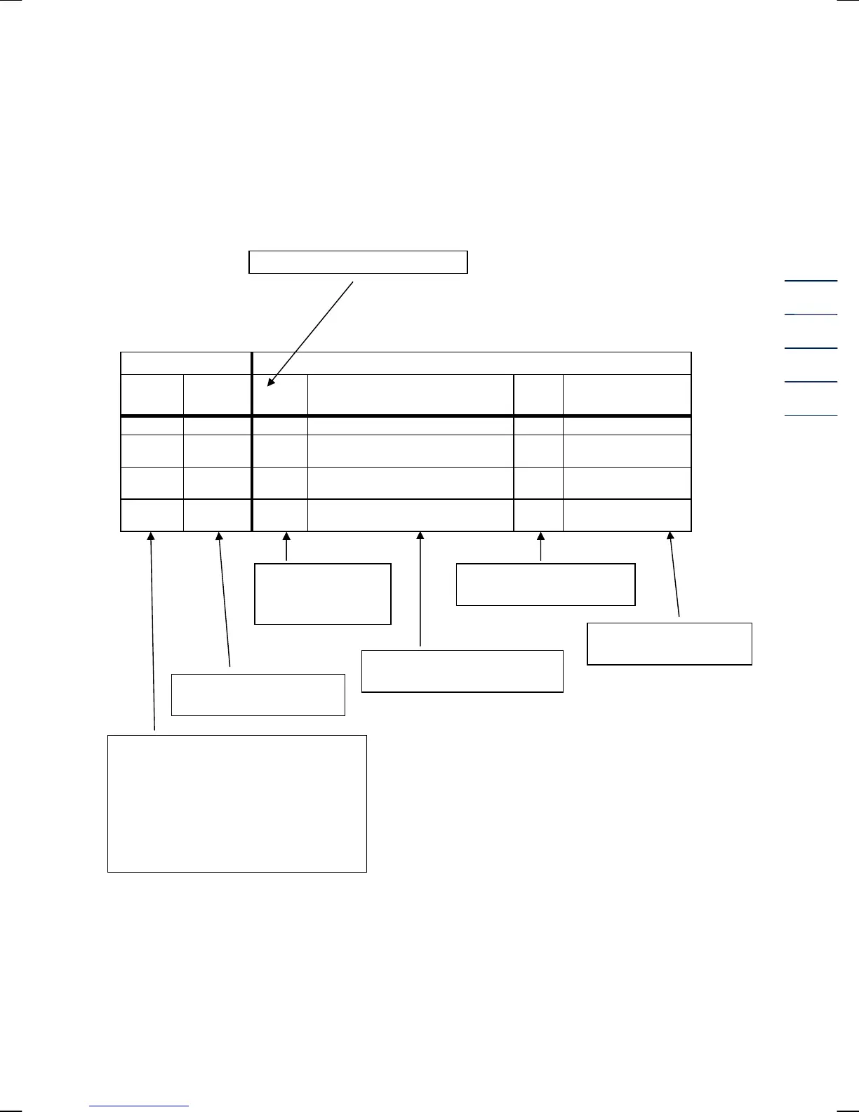
Description of individual columns
Column structure
Pointer position V
Coding
Coordinate
/ Line
A Description of the coordinate Unit Special feature
S 1 Nm3 Main totalizer, volume at base conditions m3
S 2 m3
Main totalizer, volume at measurement
conditions
m3
S 3 VbD
Disturbing quantity totalizer, volume at
base conditions
m3
S 4 VmD
Disturbing quantity totalizer, volume at
measurement conditions
m3
The calibration switch is realized by a screw on the left (EC 24) or right (EC 21) side of the device
(see fig. on page 10). For opening the calibration switch just unscrew the screw by some turns until
the text “Input” is blinking in the display. Then all parameters coded with “S” or “C” can be
changed.
Designation of columns A to O
Press the above function key and then the ► key once.
Unit of the value displayed
or programmed
Abbreviated
designation of the
matrix field
Explanatory notes on a
coordinate field
Field designation shown in the
display of the EC 21 / EC 24
Designation of the
column line
Coding of the matrix fields
H = Header
D = Display value
C = Access to a data field which is
protected by the user code
S = Access to a data field which is
protected by the calibration switch
Note: In the software version 1.0 the
user code is not yet implemented. To
change parameters with “C” coding it is
necessary to open the calibration
switch!