ANNEXES
...............................................................................................................................................................................................................
...............................................................................................................................................................................................................
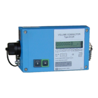
Manual EC 24 · EN05 · 2015-02
39
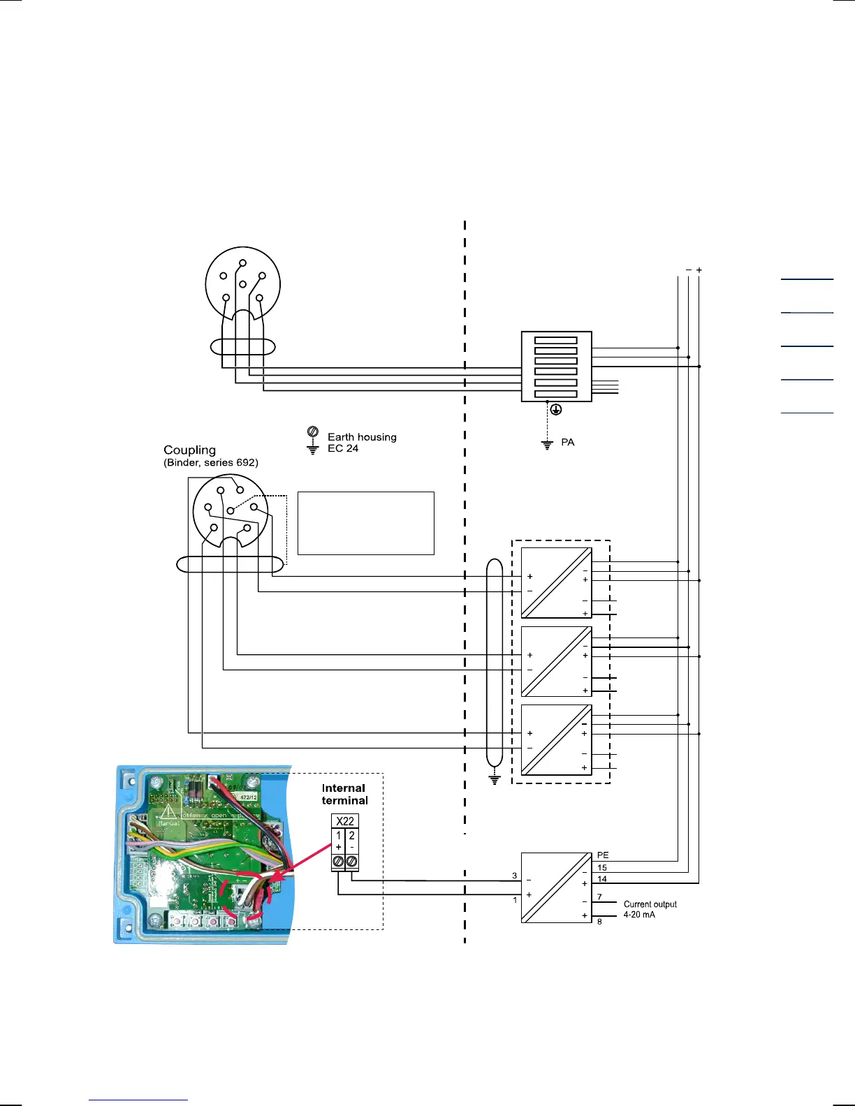
Mains-powered device
(Connection only via a current module with built-in back-up battery)
5
4
6
3
2
1
PC
5
5
5
6
6
6
7
9
7
11
11
11
12
12
12
PE
PE
PE
8
10
8
larm
HF
LF
24 V/DC
PE
6
4
3
2
1
5
Pin assignment (692):
1= LF - 4= LF +
2= Alarm - 5= Alarm +
3= HF - 6= HF +
Isolating device
Type: Datcom-K3
Hazardous area Safe area
Connector,
Binder Series 423
Isolating amplifiers
KFD2-SOT-Ex2 (24 V/DC)
Supply unit
e.g. KFD2-STC4-Ex1 (24 V/DC)
RS 485
LIYCY 2x2x0.5 mm blue
2
Pulse outputs
LIYCY 3x2x0.75 mm blue
2
Current output
LIYCY 2x0.75 mm
blue
2
* If 2-channel isolating amplifiers
are used, the two inputs must
be separated!
Connector,
Binder Series 713
(brown)
(white)