Rhein-Nadel Automation GmbH 10
VT-BA-SCU1000-2000-EN_2019 / 27.06.2019 SJ
4.3. Start/Stop by external controller
With the default setting the vibrating drive is started/stopped by the power switch of the controller. The external ena-
bling input makes it possible to start and stop the vibrating drive by a higher-level control system.
There are two options provided for external enabling:
Voltage signal:
This type of enabling should be preferred.
If a direct voltage between 16 and 30 V is available with the correct polarity the vibrating drive starts. The input is pro-
tected against polarity reversal.
Observe the following directives:
• Cable length max. 10m.
• Avoid cable routing in the immediate vicinity of high-energy switching devices or strong interference fields.
Floating contact:
If no 24 V signal is available, enabling is also possible via a floating contact. Feed the connecting cable through a ca-
ble gland into the controller and connect it to the terminal block provided for this purpose. Closing of the contact ena-
bles the controller and starts the vibrating drive.
Observe the following directives:
• Cable length max. 5m.
• Use shielded cable for lengths of 3m and more.
• Avoid cable routing in the immediate vicinity of high-energy switching devices or strong interference fields.
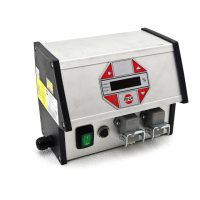
SCU2000:
Connection for the 24V signal is made with connector XS21.
See also connection diagram of SCU2000, chapter 5.
Use terminal block X2 to connect the floating contact inside the controller.
Remove the top blanking plug (M16x1.5) and replace it with a plastic cable gland (M16x1.5).
The cable gland must be suitable for the cable diameter and have a thread length of 8mm max.
Afterwards the fuse behind the gland can only be reached by opening the device.
Insert a cable with a cross-section of 2x0.25mm² min. to 2x0.5mm². max. Connect the cores to terminals 7 and 8. See
also illustration on page 11 (position of terminals inside device).
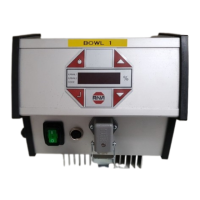
SCU1000:
For both external enabling options the signal cables must be connected to terminal block X2 inside the controller.
Remove the blanking plug from one of the two top holes and install the M8x1 cable gland (supplied with the SCU1000)
with lock nut. Insert a cable with a cross-section of 2x0.25mm² min. to 2x0.5mm² max. The max. cable diameter is
5mm. Use terminals 5 (+24V) and 6 (GND) to connect the external enabling voltage. Use terminals 7 and 8 to connect
the floating contact. See also illustration on page 11 (position of terminals inside device).
 Loading...