5-4-6
MAIN BEARING COVER
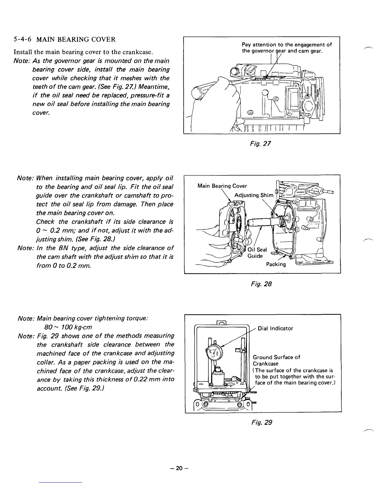
Install the main bearing cover
to
the.crankcase.
Note:
As
the'governor gear
is
mounted on the main
bearing cover side, install the main bearing
cover while checking that
it
meshes with the
teeth
of
the cam gear. (See Fig. 27.) Meantime,
if
the oil seal need be replaced, pressure-fit a
new oil seal before installing the main bearing
cover.
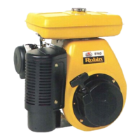
Note: When installing main bearing cover, apply oil
to the bearing and oil seal
lip.
Fit the oil seal
guide over the crankshaft
or
camshaft to
pro-
tect the oil seal lip from damage. Then place
the main bearing cover
on.
Check the crankshaft
if
its
side clearance
is
0
-
0.2
mm; and if not, adjust
it
with the ad-
justing shim. (See Fig. 28,)
Note: In the
BN
type, adjust the side clearance of
the cam shaft with the adjust shim
so
that
it
is
from
0
to
0.2
mm.
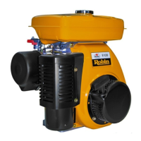
Note: Main bearing cover tightening torque:
Note: Fig.
29
shows one of the methods measuring
the crankshaft side clearance between the
machined face
of
the crankcase and adjusting
collar.
As
a paper packing
is
used
on
the ma-
chined face of the crankcase, adjust the clear-
ance
by
taking this thickness of0.22
mm
into
account. (See Fig.
29.)
80
-
100
kg-cm
-1
Pay attention to the engagement of
the governor ear and cam gear.
It
Fig.
27
Fig.
28
1
(*-*
Dial Indicator
Ground Surface
of
(The surface
of
the crankcase
is
to be put together with the sur-
face of the main bearing cover.)
Fig.
29
-
20
-