5-4-3
ASSEMBLING
ORDER
and
PRECAUTIONS
1)
Place the tappets into the crankcase.
..
NOTE:
The intake and exhaust tappets are the same,
but mark them differently when disassembl-
ing because of different
valve
clearances; and
fit
them into their origianl place. Apply oil to
the tappets beforehand.
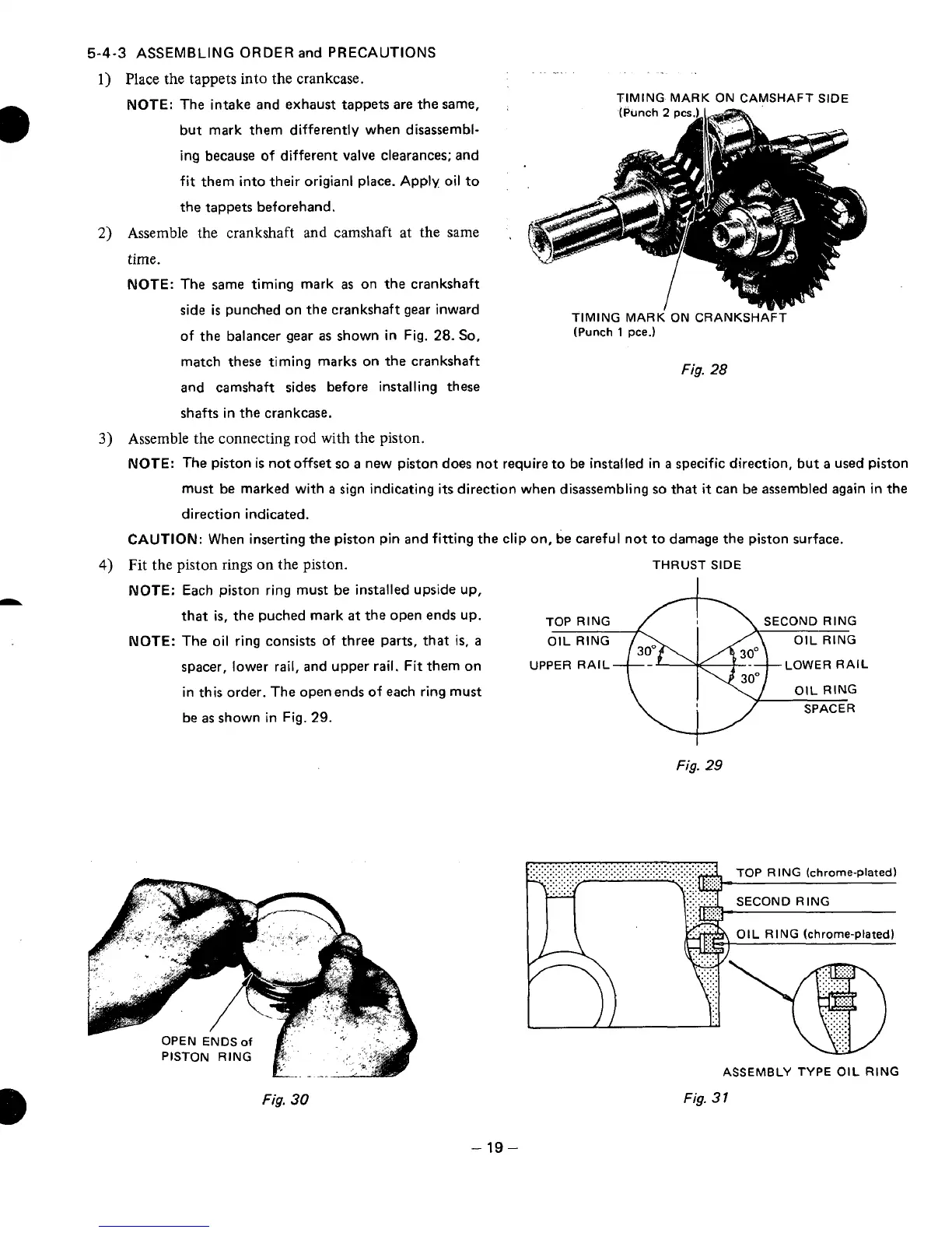
Assemble the crankshaft
and
camshaft at the same
time.
NOTE:
The same timing mark
as
on the crankshaft
side
is
punched on the crankshaft gear inward
TIMING MARK ON CAMSHAFT SIDE
(Punch
2
pcskl
TIMING
MARK ON
CRANKSHA??
of the balancer gear
as
shown in Fig.
28.
So,
(Punch
1
pce.)
match these timing marks on the crankshaft
and camshaft sides before installing these
shafts in the crankcase.
3)
Assemble the connecting
rod
with
the piston.
Fig.
28
NOTE:
The piston
is
not offset
so
a
new piston does not require to
be
installed in
a
specific direction, but
a
used piston
must be marked with
a
sign indicating its direction when disassembling
so
that
it
can be assembled again in the
direction indicated.
CAUTION:
When inserting the piston pin and fitting the clip on, be careful not to damage the piston surface.
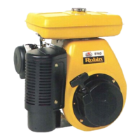
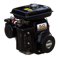
4)
Fit
the
piston rings on the piston.
THRUST SIDE
NOTE:
Each
piston ring must be installed upside
up,
that
is,
the puched mark
at
the open ends up.
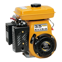
NOTE:
The oil ring consists
of
three parts, that is,
a
spacer, lower rail, and upper rail.
Fit
them on
UPPER RAIL LOWER
RAIL
in this order. The open ends of each ring must
be
as
shown in Fig.
29.
Fig.
29
ASSEMBLY TYPE
OIL
RING
Fig.
30
Fig.
3
1
-
19-