l
TOLERANCE OF NEWLY INSTALLED PARTS
Thrust directional tolerance between the cylinder and piston skirt
I
0.008L - 0.047 L
I
I
Top ring
I
0.2 L - 0.4L
I
Clearance of piston ring joint Second ring
0.2L - 0.4L
Oil ring
0.05L - 0.25L
Spare rings
Top ring
0.09OL - 0.135L
I
Clearance between piston ring Second ring
, Oil ring
0.06OL - 0.105L
O.OlOL - 0.065L
Spare ring
Clearance between connecting
rod large end and crankpin
Inside and outside diameter
clearance
Side clearance
0.037L - 0.063L
O.lL-0.7L
Clearance between connecting rod small end and piston pin 1 O.OlOL - 0.029L
I
I
Clearance between piston pin and piston pin hole
1 0.009T - O.OlOL
I
Table 10-2
L = Loose T = Tight
NOTE: The clearance between the piston and cylinder is checked by measuring the clearance between the
piston and cylinder skirt.
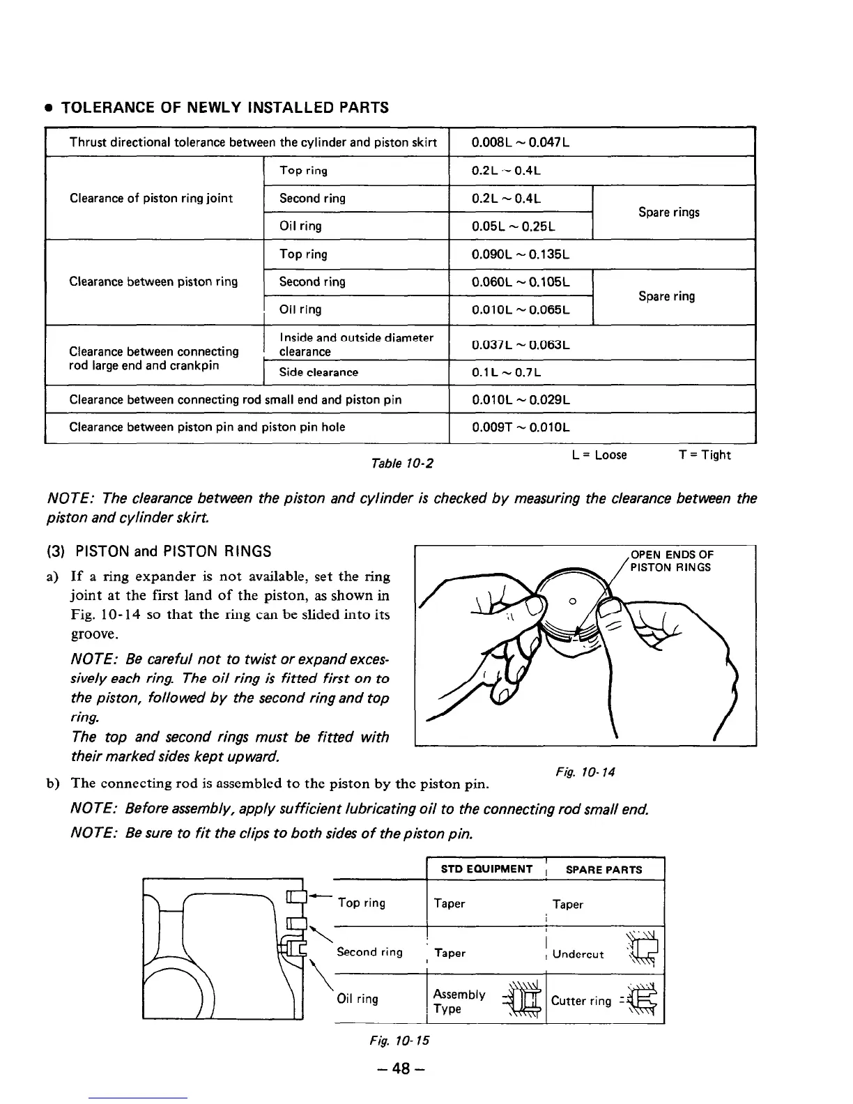
(3) PISTON and PISTON RINGS
a) If a ring expander is not available, set the ring
joint at the first land of the piston, as shown in
Fig. lo- 14 so that the ring can be slided into its
groove.
NOTE: Be careful not to twist or expand exces-
sively each ring. The oil ring is fitted first on to
the piston, followed by the second ring and top
ring.
The top and second rings must be fitted with
their marked sides kept up ward.
OPEN ENDS OF
PISTON RINGS
Fig. IO- 74
. ,
b) The connecting rod is assembled to the piston by the plsron pm.
NOTE: Before assembly, apply sufficient lubricating oil to the connecting rod small end.
NOTE: Be sure to fit the clips to both sides of the piston pin.
a
a
Q
I
STD EQUIPMENT ;
SPARE PARTS
I
- Top ring
Taper
Taper
\
Second ring
\
Oil ring
Fig. lo- 15
- 48 -
 Loading...


