(4) INSTALLING THE CRANKCASE
The connecting rod is put into the cylinder while
holding it with the piston ring guide, as shown in Fig.
lo- 16 (in the case that a piston ring guide is not
available, press rings inward with fingers and at the
same time, strike down the piston: using a wooden
block). The connecting rod must be mounted in
place with its @and MA marks directed to the ball
bearing side of the crankcase.
NOTE: Apply a sufficient quantity of oil to the pis-
ton rings, connecting rod surfaces, and cylinder.
NOTE: The top, second and oil rings are fitted to
the piston with their ring joints arranged 90 ‘0 ff each
adjacent joint.
(5) INSTALLING THE CONNECTING ROD
MAJOR END CAP
a) Manually turn the crankshaft until the piston
reaches top dead center. Gently strike down the
piston head until the connecting rod touches the
crankpin to install the connecting rod major end
cap.
b) The cap is installed with the oil scraper position-
ed right-downward. (See Fig. lo- 17.)
NOTE: Be sure to use a new lock washer; and
carefully bend the washer correctly.
NOTE: When the cap has been installed, turn
the crankshaft to see if the connecting rod moves
smoothly.
GUIDE
Fig. lo- 16
Fig. lo- 17
NOTE: The correct torque for installing the connecting rod major end cap is 60 to 80 kg-cm.
NOTE: See Table 10-2 for details regarding the clearances between the piston, piston rings, and connect-
ing rod and their counterparts.
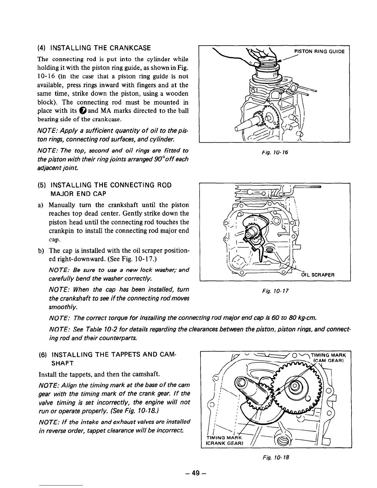
(6) INSTALLING THE TAPPETS AND CAM-
SHAFT
Install the tappets, and then the camshaft.
NOTE: Align the timing mark at the base of the cam
gear with the timing mark of the crank gear. If the
valve timing is set incorrectly, the engine will not
run or operate properly. (See Fig. lo- 18.1
NOTE: If the intake and exhaust valves are installed
in reverse order, tappet clearance will be incorrect.
SEAR)
Fig. lo- 78
-49-
 Loading...


