(7) INSTALLING THE MAIN BEARING COVER
Install the main bearing cover to the crankcase.
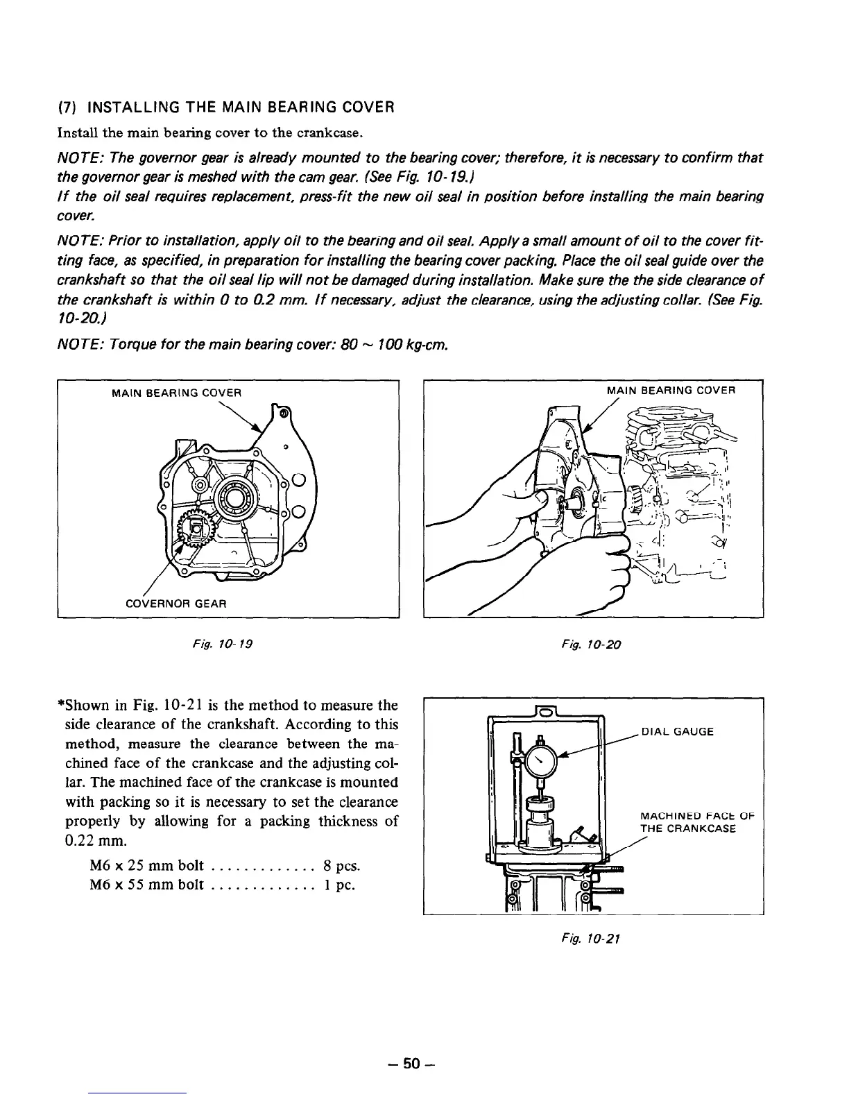
NOTE: The governor gear is already mounted to the bearing cover; therefore, it is necessary to confirm that
the governor gear is meshed with the cam gear. (See Fig. IO- 19.)
If the oil seal requires replacement, press-fit the new oil seal in position before installing the main bearing
cover.
NOTE: Prior to installation, apply oil to the bearing and oil seal. Apply a small amount of oil to the cover fit-
ting face, as specified, in preparation for installing the bearing cover packing. Place the oil seal guide over the
crankshaft so that the oil seal lip will not be damaged during installation. Make sure the the side clearance of
the crankshaft is within 0 to 0.2 mm. If necessary, adjust the clearance, using the adjusting collar. (See Fig.
10-20.)
NOTE: Torque for the main bearing cover: 80 - 100 kg-cm.
MAIN BEARING COVER
I
MAIN BEARING COVER
COifERNOR GEAR
I
Fig. lo- 19
Fig. lo-20
*Shown in Fig. lo-21 is the method to measure the
side clearance of the crankshaft. According to this
method, measure the clearance between the ma-
chined face of the crankcase and the adjusting col-
lar. The machined face of the crankcase is mounted
with packing so it is necessary to set the clearance
properly by allowing for a packing thickness of
0.22 mm.
M6 x 25 mm bolt . . . . . . . . . . . . . 8 PCS.
M6 x 55 mm bolt . . . . . . . . . . . . . 1 pc.
DIAL GAUGE
MACHINED FACE
THE CRANKCASE
OF
Fig. lo-21
- 50 -
 Loading...


