(8) INSTALLING THE INTAKE AND EXHAUST VALVES
Prior to installing, remove carbon and gum deposits from the valve, valve seat, intake and exhaust ports, and
valve guide.
NOTE: If the valve face is worn, replace the valve with a new one.
NOTE: if the clearance between the valve guide and valve stem is excessively large, replace the valve guide
with a new one.
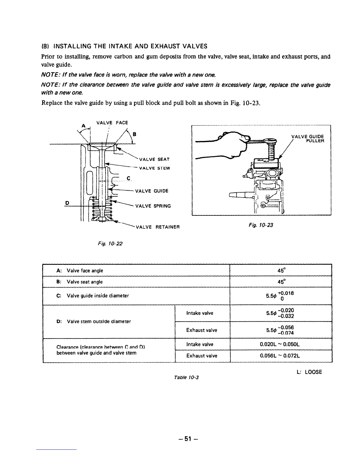
Replace the valve guide by using a pull block and pull bolt as shown in Fig. 1 O-23.
D
VALVE FACE
VALUE SEAT
VALVE STEM
VALVE GUIDE
VALVE SPRING
‘VALVE RETAINER
Fig. lo-22
.VE GUIDE
PULLER
Fig lo-23
A: Valve face angle
45O
I
B: Valve seat angle
I
45O
I
C: Valve guide inside diameter
5 5# +0.018
0
D: Valve stem outside diameter
Intake valve
5’5d’ -0.020
-0.032
Exhaust valve
5.54 -0.056
-0.074
Clearance (clearance between C and D)
between valve guide and valve stem
Intake valve
Exhaust valve
0.020L - 0.05OL
0.056L - 0.072L
Table 10-3
L: LOOSE
-51 -
 Loading...


