IDLE
CONTROL
UNIT
i
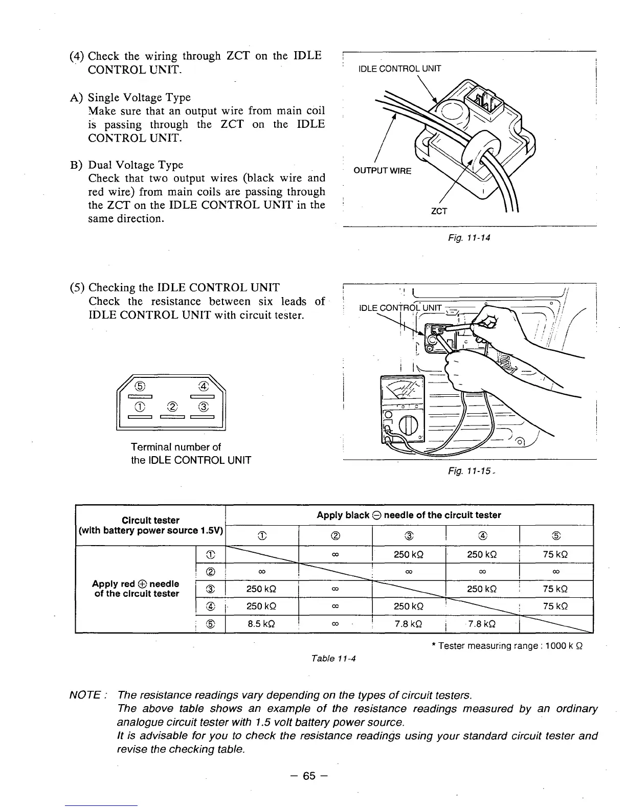
(4)
Check the wiring through ZCT on the IDLE
CONTROL UNIT.
A)
Single Voltage Type
Make sure that an output wire from main coil
is
passing through the. ZCT on the IDLE
COKTROL UNIT.
B)
Dual Voltage Type
Check that two output wires (black wire and
red wire) from main coils are passing through
the ZCT on the IDLE COKTROL UKIT in the
same direction.
(5)
Checking the IDLE CONTROL UNIT
Check the resistance between six leads
of
IDLE CONTROL UNIT with circuit tester.
11”-
I
Terminal number
of
the
IDLE
CONTROL UNIT
I
/
ZCT
\\\
Fig.
17-14
IDL
Fig.
11-15-
Circuit tester
(with battery power source
1
SV)
Apply black
3
needle
of
the circuit tester
1
I
:g
A
.a
n
L.
\I
I
250 kR
.
250 kR
i
75kQ
!
Q
1
00
22
I
00
Apply red
@
needle
!
I
of
the circuit tester
3
1
250 kR
1
250 kQ 75 kR
,”.
I
75 kR
I
:
I-
250 kR
-
.n
f
.&
I
8.5 kR
30-
!
7.8kR 7.8kQ
11
*
Teste:
measuring
range
:
1000
k
0
Tabi‘e
11-4
NOTE
:
The resistance readings vary depending on the types
of
circuit testers.
The above table shows an example
of
the resistance readings measured by an ordinary
analogue circuit tester with
1.5
volt battery power source.
It is advisable
for
you to check the resistance readings using your standard circuit tester and
revise the checking table.
-
65
-