-
28
-
9-4 STATOR
Disengage connectors on the wires from stator
and check the resistance between wires with a
“Dr. Robin” or a circuit tester referring to the fol-
lowing table.
NOTE : If the circuit tester is not sufficiently accurate, it may not show the values given and may give
erroneous readings. Erroneous readings will also occur when there is a wide variation of resis-
tance among coil windings or when measurement is performed at ambient temperatures differ-
ent from 20
°
C (68
°
F).
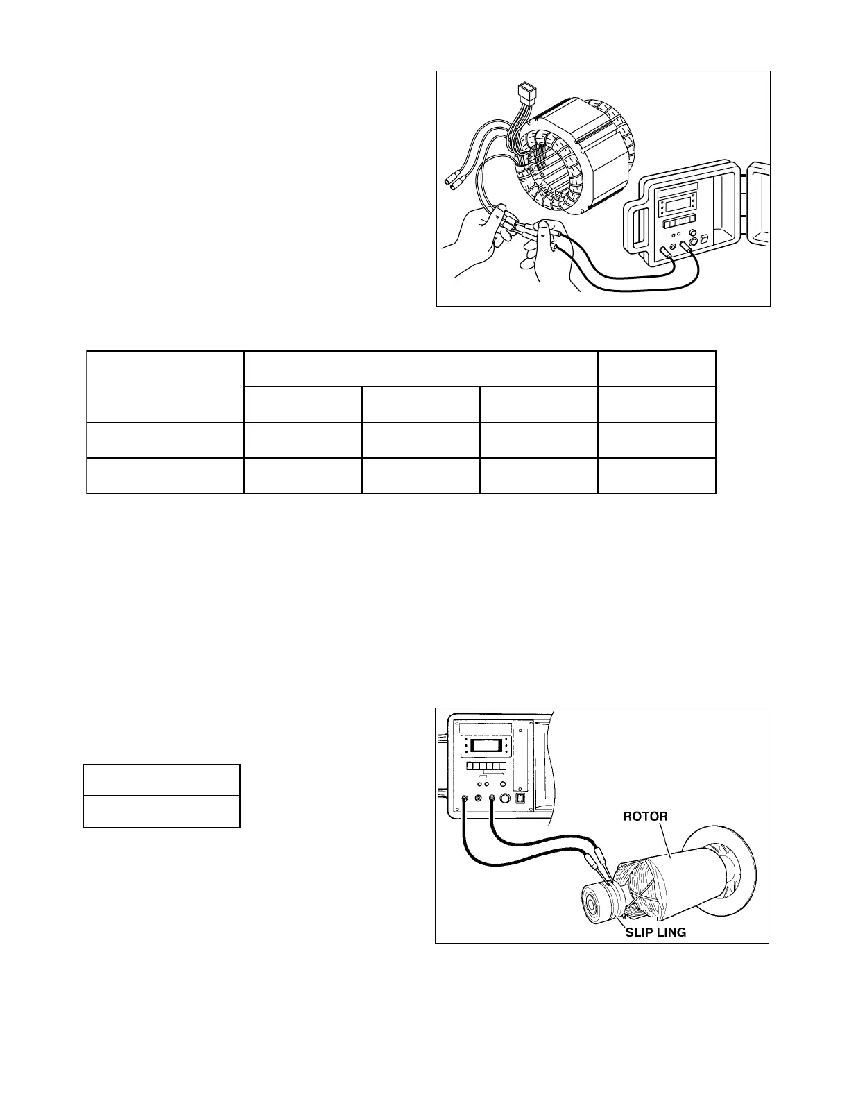
9-5 ROTOR ASSEMBLY
1) Field coil
Remove the brush holder and measure resistance
between the slip rings.
NOTE : If the circuit tester is not sufficiently accu-
rate, it may not show the values given and may
give erroneous readings.
Erroneous reading will also occur when there is a
wide variation of resistance among coil windings
or when measurement is performed at ambient
temperatures different from from 20
°
C (68
°
F).
Fig. 9-4
Table. 9-1
Fig. 9-5
egatloV-zH
liocrotatSliocCD
etihW-deReulB-kcalBneergthgiL/etihWnworB/nworB
011-05 〜 04222.0 Ω 12.0 Ω 97.0 Ω 31.0 Ω
042/021-0661.0 Ω 61.0 Ω 16.0 Ω 11.0 Ω
ecnatsiseR
62.7 Ω
 Loading...


