-
54
-
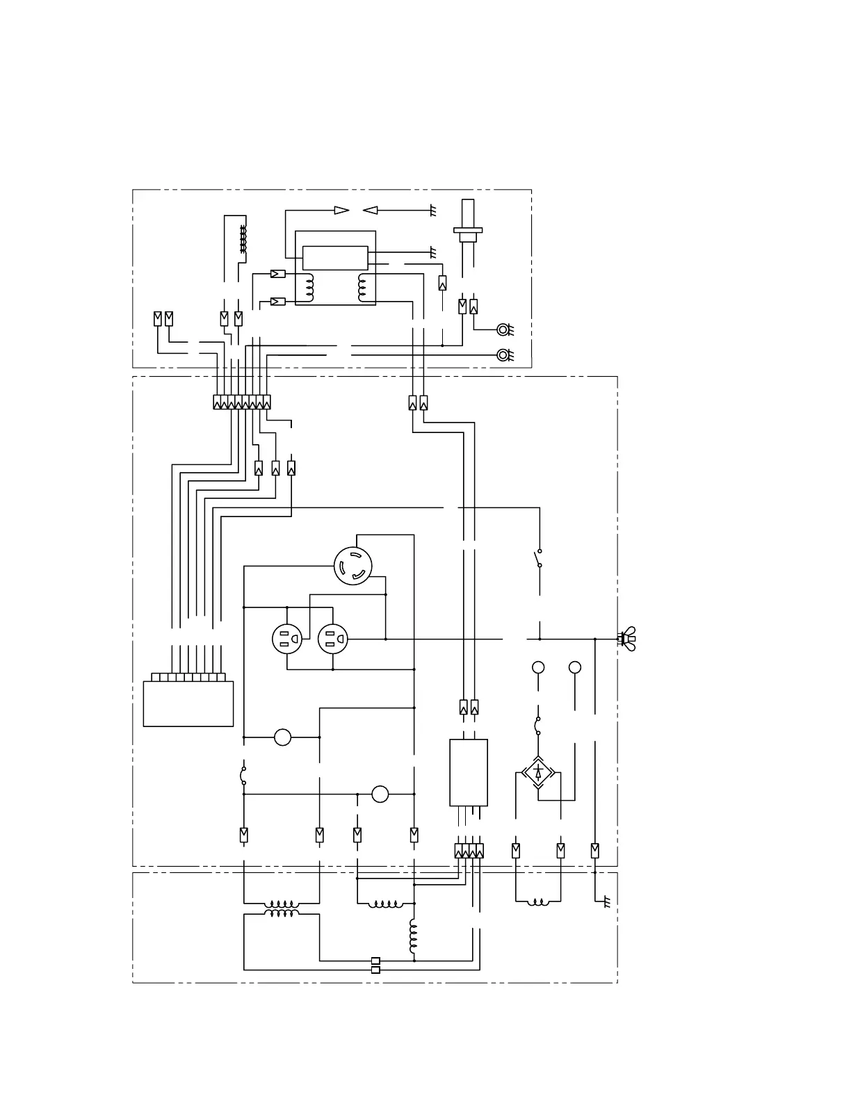
12. WIRING DIAGRAM
Recoil starter model (50Hz-110V, 60Hz-110V, 60Hz-120V)
Wiring color cord
Blk : Black Brn/W : Brown/White R : Red
Blk/W : Black/White Grn : Green W : White
Blu : Blue Grn/W : Green/White Y : Yellow
LBlu : Light blue Grn/Y : Green/Yellow Org : Orange
Brn : Brown LGrn : Light green Gry : Gray
+
-
8
9
1
5
3
6
7
4
GENERATOR CONTROL BOX
Field Winding
AC Winding 2 AC Winding 1
DC Winding
2
Blu
Blu
Blk/W
Grn/W
Grn/W
Blk
Grn/Y
Sub coil
LGrn
Brn
LGrn
Brn
R
W
Brn
Brn
Or
Brn/W
DC output
terminal
Circuit breaker
Diode stack
Assy
AVR
Earth
(Ground) terminal
Grn/Y
Grn/Y
Engine switch
Grn/Y
REC2
REC1
ENGINE
Blk
Blk
Blk
Blk/W
Y
Y
Oil sensor
Grn/Y
Blk
Grn/W
Spark plug
Grn / Y
W
W
Blu
Blu
Blu
Blu
Fuel cut solenoid
Grn/W
Charge
coil
Exciter
coil
Ignition coil
Brush (+)
Brush (
-
)
Y
Y
Y
Y
Blk
Fuel
cut unit
Blu
R
Blk
W
AC output
receptacle
(
120V
)
AC output
receptacle
(
120V
)
P
V
Blu
R
Blk
No-fuse breaker
Pilot
lamp
Voltmeter
W
 Loading...


