-
48
-
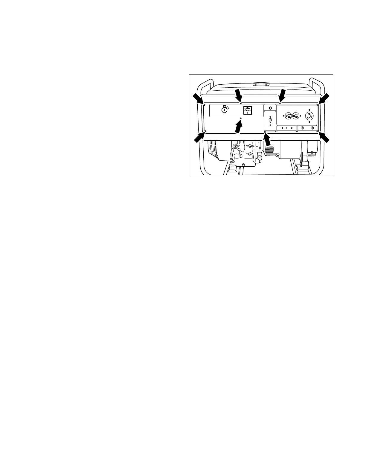
10-3-9 CONTROL PANEL
Mount the control panel assembly to the control box.
Refer to Section 10-4 for disassembly, checking and reassembly procedures of the control panel.
(1) Connect the wires from the control panel and
the engine.
(2) Connect the wires drawn out from the stator to
the wires from the control panel.
NOTE : Connect the wires of the same color.
(3) Press the upper end of the bushing into the
bottom window of the control panel.
(4) Mount the control panel to the control box.
M5 x 12 mm bolt and washer Ass’y . . . 8 pcs.
10-4 CHECKING, DISASSEMBLY and REASSEMBLY of the CONTROL PANEL
10-4-1 CHECKING OF THE CONTROL PANEL
Dismount the control panel from frame. Remove the control panel and check each components and
wiring. Refer to Section 9 for the detail of checking procedure for the components in the front panel.
10-4-2 DISASSEMBLY
(1) Remove the control panel from the control box.
M4 screw . . . 8 pcs.
(2) Disconnect the connectors on the wires to detach the control panel.
(3) After disconnecting individual wires, remove the control panel components.
NOTE : Full power switch and pilot lamp have their wires soldered. Unsolder them to remove those parts
if necessary.
Fig. 10-35
 Loading...


