-
50
-
11. TROUBLESHOOTING
11-1 NO AC OUTPUT
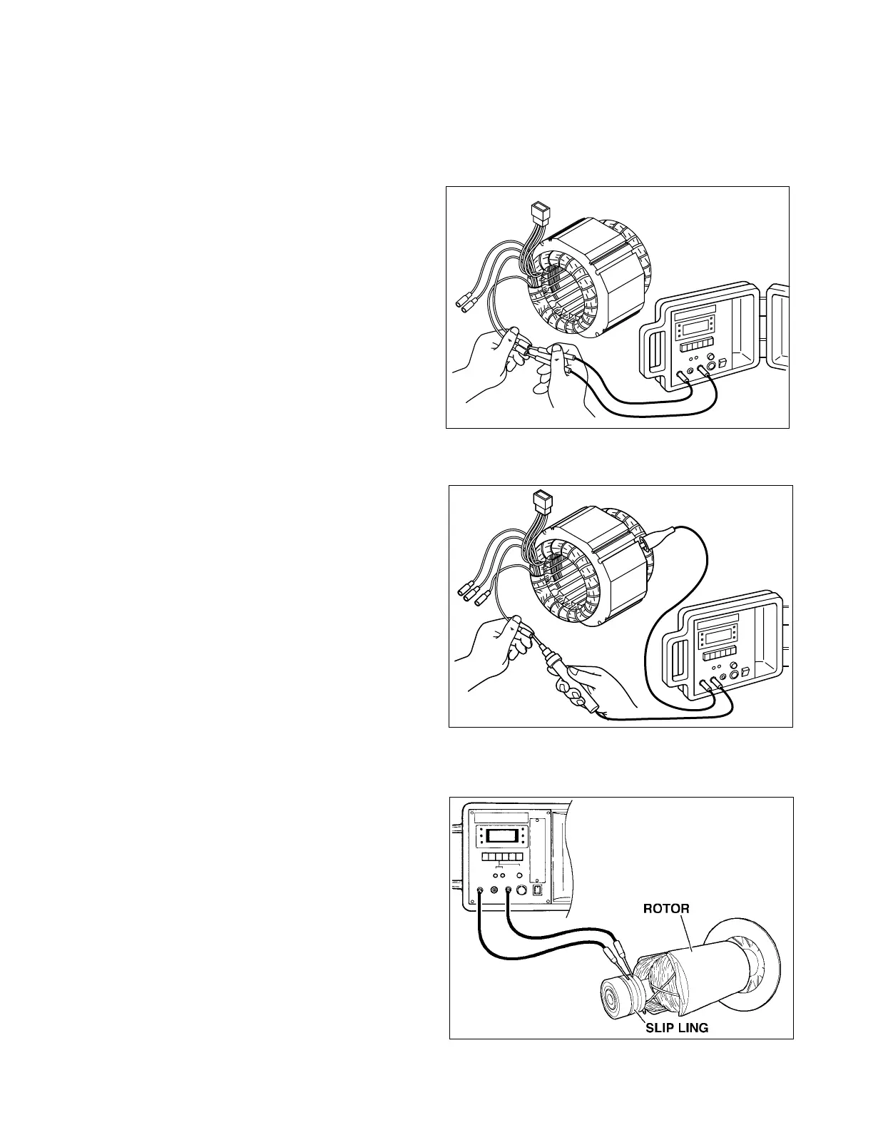
11-1-1 CHECKING STATOR
(1) Remove control panel and disconnect stator
wires at the connectors.
(2) Measure the resistance between terminals on
stator leads. (See Fig.11-1) Refer to Table 9-1
of Section 9-4 STATOR for normal resistance.
If stator is faulty, replace it with a new one.
(3) Check the insulation resistance between sta-
tor core and each stator lead using a Dr. Robin
generator tester in megger tester mode or a
megger tester. (Fig. 11-3)
If insulation is bad, replace stator with a new
one.
11-1-2 CHECKING ROTOR
1) Field coil
Remove the brush holder and measure resistance
between the slip rings. Refer to Section 9-5 RO-
TOR ASSEMBLY for normal resistance.
NOTE : If the circuit tester is not sufficiently accu-
rate, it may not show the values given and may
give erroneous readings.
Erroneous reading will also occur when there is a
wide variation of resistance among coil windings
or when measurement is performed at ambient
temperatures different from from 20
°
C (68
°
F).
Fig. 11-2
Fig. 11-1
Fig. 11-3
 Loading...


