Features and technical data
Installation, use and maintenance manual – Next-R
17
1
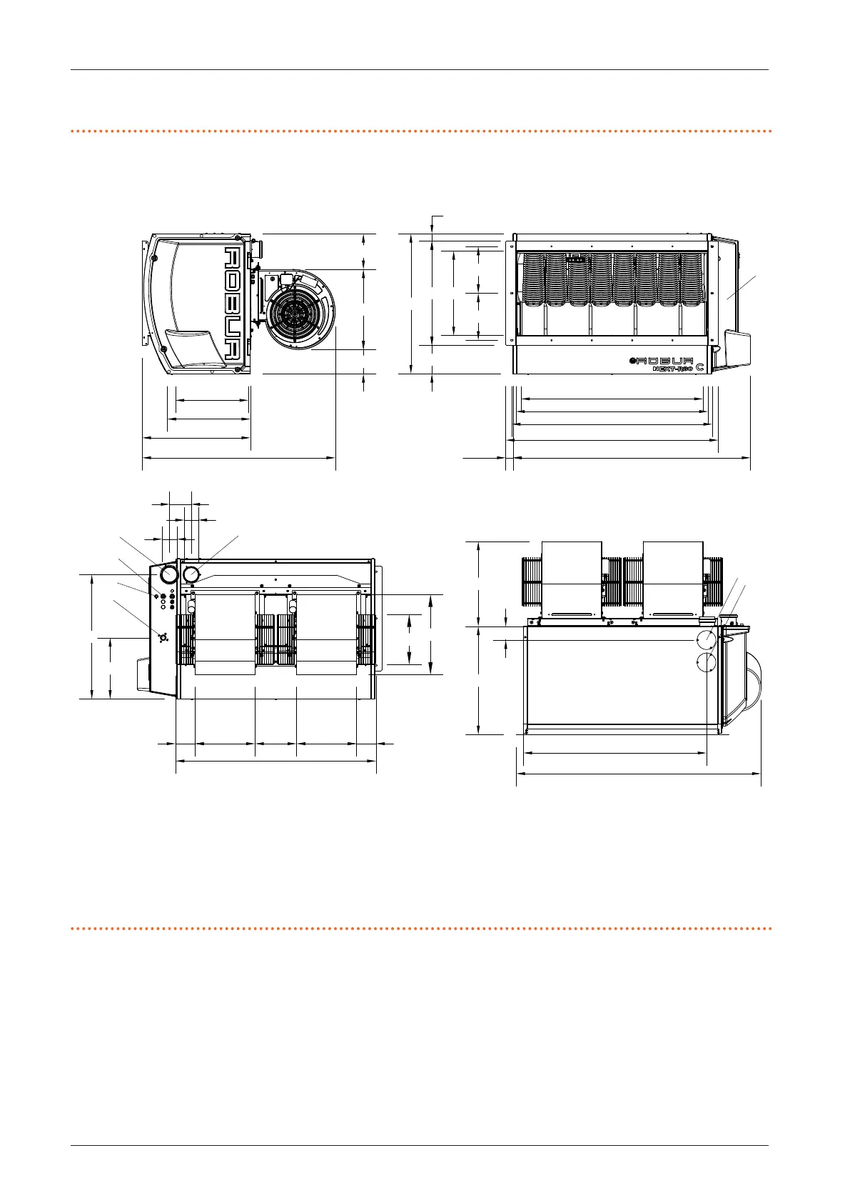
1.2.2.4 R80 C
Figure1.10 Unit dimensions
1 Flue gas exhaust
2 Combustion air inlet
3 Power supply cables input
4 Gas connection 3/4" F
5 Thermoformed door
6 Limit thermostat
7 Flue gas exhaust blind cover, alternative to the rear one (1)
8 Blind cover for access to the fan thermostat
(*) Holes for xing to the support bracket
1319
40
1180
1113
1067
777
580
157
469
260
260
1359
601
472
1113
108
333 230 333
108
446
278
12
3
4
6
80
80
340
690
446
197
134
461
601
1072
1010 (*)
405 (*)
120
7
8
76
1017
1.2.3 Vertical downow gas unit heaters
The dimensions of the vertical downow gas unit heaters
are identical to those of the corresponding axial models
(Paragraph 1.2.1
p.8
).
Figure 1.11
p.18
below details the centre distances be-
tween the vertical suspension brackets for the dierent
models of vertical downow gas unit heaters.
The R15 and R20 gas unit heaters are not equipped with
vertical suspension brackets, as the installation with ver-
tical downow is carried out by means of the revolving
bracket OSTF020 (available as an optional, Paragraph
2.5.4
p.28
).
 Loading...

