Transport and positioning
Installation, use and maintenance manual – Next-R
25
2
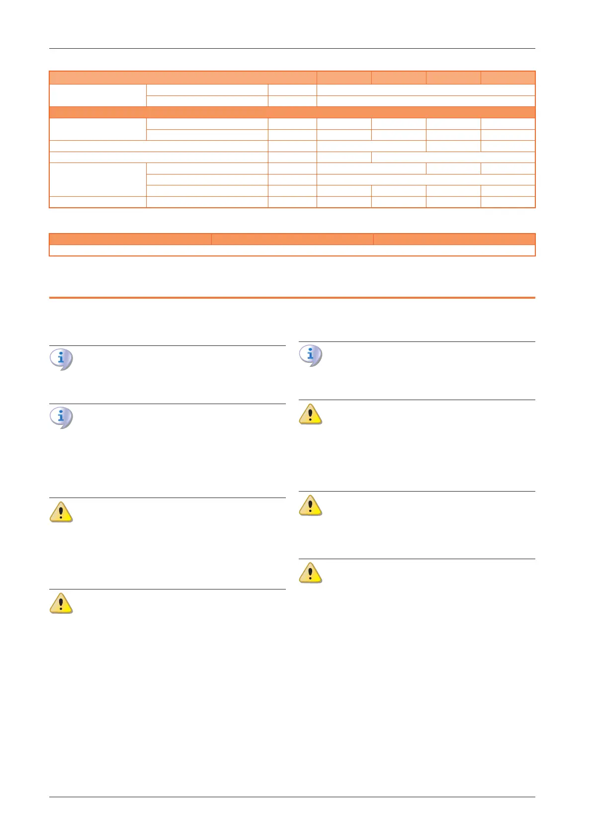
R30 C R40 C R50 C R80 C
Degree of protection
fan motor IP 44
appliance IP 20
Installation data
Air ow
at maximum available head m³/h 1900 3400 4700 7000
nominal (Delta T = 15 °C) m³/h 2900 4000 5350 8550
maximum useful pressure head Pa 120 240 120
minimum pressure drop on heat ow delivery Pa 0 50
Dimensions
width mm 774 968 1359
height mm 777
depth mm 1031 1072 1138 1072
Weight in operation kg 68 80 92 129
Vertical downow models
R30 V R40 V R50 V
The technical data of these models are identical to those of the corresponding axial models, with the exception of the installation height
2 TRANSPORT AND POSITIONING
2.1 WARNINGS
Damage from transport or installation
The manufacturer shall not be liable for any dam-
age during appliance transport and installation.
On-site inspection
Upon arrival at the site, ensure there is no transport
damage on packing, metal panels or to the ther-
moformed door.
After removing the packing materials, ensure the
appliance is intact and complete.
Packing
Only remove the packing after placing the appli-
ance on site.
Do not leave parts of the packing within the reach
of children (plastic, polystyrene, nails...) since they
are potentially dangerous.
Weight
The lifting equipment must be suitable for the load.
Lift up the unit and secure it to its support bracket
(Paragraph 2.5
p.27
).
2.2 HANDLING
2.2.1 Handling and lifting
▶
Always handle the appliance in its packing, as deliv-
ered by the factory.
▶
Comply with safety regulations at the installation site.
2.3 APPLIANCE POSITIONING
The unit must be installed in the room to be heated.
2.3.1 Where to install the appliance
The wall or structure on which the unit is to be in-
stalled must be load-bearing or, in any case, suit-
able for supporting its weight.
Installation must not be made on walls with poor
strength that do not guarantee adequate resist-
ance to the stresses produced by the unit. The
manufacturer does not assume any responsibility
if the appliance is installed on surfaces or walls that
are not suitable for supporting its weight.
Vertical downow gas unit heaters must be in-
stalled with the warm air delivery downwards. The
gas unit heater must be horizontal in relation to its
longitudinal axis.
The appliance's ue gas exhaust must not be im-
mediately close to openings or air intakes of build-
ings, and must comply with safety and environ-
mental regulations.
To obtain the maximum system eciency it is advisable to
comply with the following rules:
▶
Make sure that the air ow does not directly impinge
on the sta (by tilting the grille louvres appropriately).
▶
Take any obstacles into account (pillars or other).
▶
Consider length of throw of the unit (Table 1.2
p.23
).
▶
For better heat distribution in the case of multiple unit
installations, create alternate ows of warm air (see
Figure 2.1
p.26
).
▶
In some cases it may also be suitable to place the units
close to the main doors, so that they can also operate
as air barriers when doors are opened.