Electrical installer
Installation, use and maintenance manual – Next-R
35
4
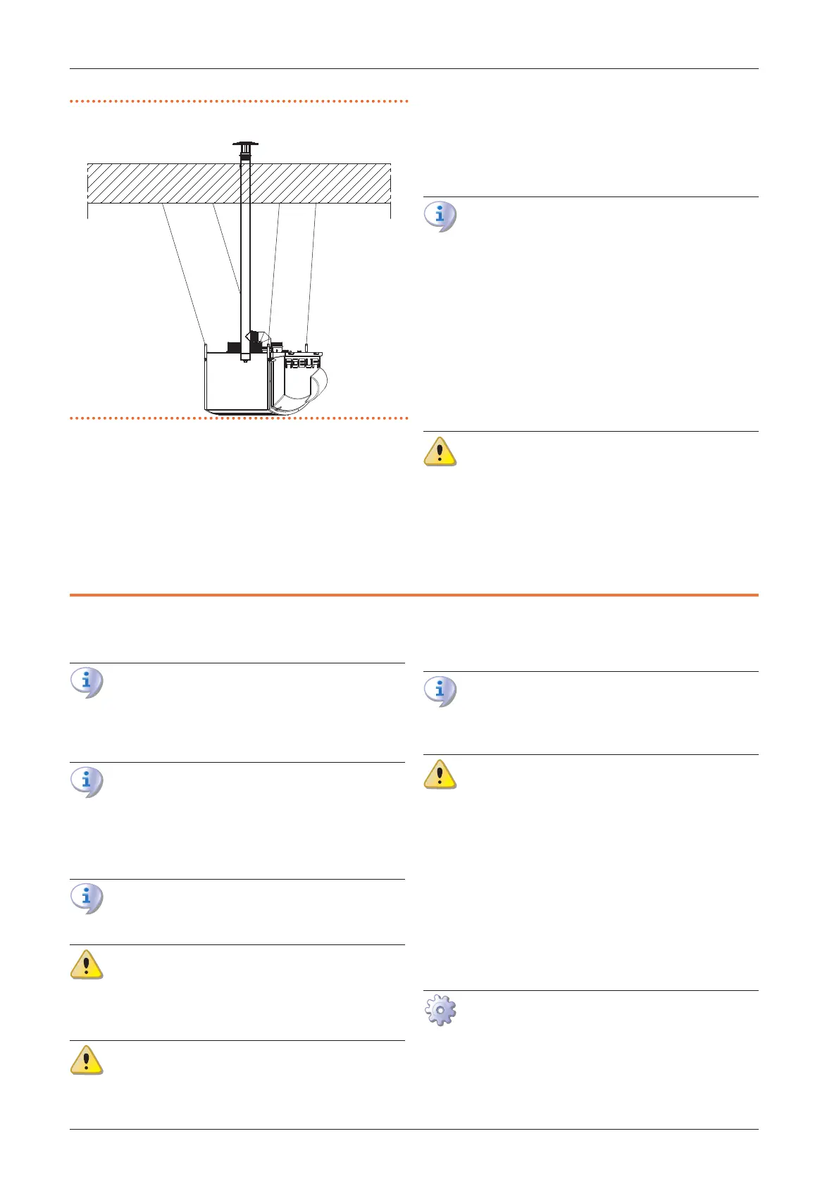
Figure3.9 Example of a vertical downow gas unit heater
installation
3.4 AIR DUCTING
Only models equipped with a centrifugal fan (Next-R C
series) can be combined with air ducting systems, which
can be positioned both on the air intake (with or without
mixing chambers) and on the delivery.
For this purpose, the delivery outlet of the Next-R C gas
unit heaters is provided with xing anges for the delivery
air ducting.
Refer to the Paragraph 1.2.2
p.14
for the dimensions of
the ange connection.
In order to avoid vibrations (possible source of
noise and mechanical failures), it is advisable to
install anti-vibration connections, easily removable
for maintenance operation, at the connection be-
tween the gas unit heater and the air duct.
Set up the air ducting using a traditional suciently
smooth sheet metal duct.
The insulation of the duct must be assessed, in order to
avoid heat losses.
For the dimensioning of the air duct, consider the data
of air ow and available head of the fan, summarized in
Table 1.2
p.23
.
Minimum pressure drop on heat ow delivery
In order to grant that the centrifugal fan operates
within the operating limits in any situation, it is
mandatory to ensure a minimum pressure drop on
the air delivery. The minimum pressure drop values
are detailed in Table 1.2
p.23
.
4 ELECTRICAL INSTALLER
4.1 WARNINGS
General warnings
Read the warnings in Chapter III
p. 4
, provid-
ing important information on regulations and on
safety.
Compliance with installation standards
Installation must comply with applicable regula-
tions in force, based on the installation Country
and site, in matters of safety, design, implementa-
tion and maintenance of electrical systems.
Installation must also comply with the manufactur-
er's provisions.
Live components
After placing the appliance in the nal position,
and prior to making electrical connections, ensure
not to work on live components.
Earthing
The appliance must be connected to an eective
earthing system, installed in compliance with
regulations in force.
It is forbidden to use gas pipes as earthing.
Cable segregation
Keep power cables physically separate from signal
ones.
Do not use the power supply switch to turn the
appliance on/o
Never use the power supply switch to turn the ap-
pliance on and o, since it may be damaged in the
long run (occasional blackouts are tolerated).
To turn the appliance on and o, exclusively use
the suitably provided control device.
4.2 ELECTRICAL SYSTEMS
Electrical connections provide:
A. Power supply (Paragraph 4.3
p.36
).
B. Control system (Paragraph 4.4
p.36
).
How to make connections
All electrical connections must be made in the connection
terminal block located near the electrical panel:
1. Ensure the appliance is not live.
2. To access the electrical board of the unit, open the
thermoformed door on the right side of the unit (detail