Heating engineer
34
3
must be mounted with a downward slope of 2 to 3
cm each 1-m length (Figure 3.7
p.34
), to prevent
condensate drops entering the unit.
If vertical ue gas exhaust pipes longer than 1,5 m
are installed, at the base of the vertically mounted
ue gas exhaust pipe a T-shaped piece must be
tted to collect the condensate, to prevent any
condensate drops from entering the gas unit
heater (Figure 3.2
p.30
).
For each 45° elbow an increment of 1,2 m in length
should be added.
Figure3.7 Slope of horizontal pipes
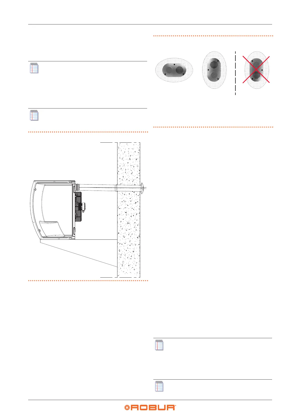
For proper installation of the wall external terminals for
the ue gas exhaust and combustion air intake, follow the
details given in Figure 3.8
p.34
.
Figure3.8 Wall terminal position
IN combustion air intake
OUT ue gas exhaust
A recommended posi-
tion (OK)
B allowed position (OK)
C position NOT allowed
(NO)
IN
OUT
IN
OUT
IN
OU
3.3.5 Example of calculation
Let's assume to install a R60 in C13 type installation (Figure
3.3
p.31
). The air/fumes system will be realized with Ø
80 separate pipes in the following way:
▶
7 m of Ø 80 ue gas exhaust pipe
▶
1 90° Ø 80 elbow on the ue gas exhaust pipe
▶
6 m of Ø 80 air pipe
It is therefore possible to proceed with the verication, re-
membering that the maximum allowed pressure drop is
100 Pa (see Table 3.11
p.33
).
▶
Ø 80 ue gas exhaust pipe
7 m x 9,2 Pa/m = 64,4 Pa
▶
90° elbow
1 x 15,4 Pa = 15,4 Pa
▶
Ø 80 air pipe
6 m x 4,4 Pa/m = 26,4 Pa
Total pressure drop = 106,2 Pa
Total pressure drop of the piping system is greater than
the maximum allowed pressure drop (100 Pa), therefore
the installation is not allowed.
The installation can be done if one of the following steps
is taken:
▶
Reduce the length of the air/fumes pipes.
▶
Increase pipe diameter, e.g. by using Ø 110. In this case
the total pressure drop would be:
7 m x 1,9 Pa/m = 13,3 Pa
1 x 4,3 Pa = 4,3 Pa
6 m x 0,9 Pa/m = 5,4 Pa
Total pressure drop = 23,0 Pa
which is therefore compatible with the maximum allowed
pressure drop.
3.3.6 Vertical downow gas unit heaters
For vertical downow gas unit heaters, at the base
of the vertically mounted ue gas exhaust pipe a
T-shaped piece must be tted to collect the con-
densate, to prevent any condensate drops from
reaching the blower (Figure 3.9
p.35
).
Pay attention to the collection and the proper con-
veying of the condensate drain.