Heating engineer
30
3
connection from the rear position to the top of the unit.
How to move the fumes gas outlet
1. Remove the gas unit heater top panel.
2. Remove the blind cover of the upper ue gas
exhaust (detail 7 in the dimensional diagrams,
Paragraph 1.2
p.8
) from the top panel.
3. Unscrew the three screws xing the ue gas ex-
haust to the rear collar.
4. Position the ue gas exhaust in the lead-in in the
top panel.
5. Secure the ue gas exhaust to the upper lead-in
with the three screws.
6. Fit the blind cover on the rear ue gas exhaust.
7. Fit the gas unit heater top panel back on.
3.3.2 Combustion air intake tting
▶
Ø 80 mm with gasket, on the rear, at the top (see di-
mensional diagrams, Paragraph 1.2
p.8
).
3.3.3 Installation types
The lengths in following Tables are intended for
installations where the air and/or ue gas exhaust
ducts follow linear paths as shown in the respec-
tive Figures. Otherwise, you must proceed with
the calculation of the pressure drop (Paragraph
3.3.4
p.32
).
If ducts other than those supplied by the manufac-
turer are used, make sure that they are suitable for
the unit on which they are installed. In particular,
the temperature class of the duct must be appro-
priate for the operating characteristics of the unit,
and must also respect the chemical-physical sta-
bility of the system itself.
In any case, use approved ducts according to the
type of installation to be made. Upon request,
Robur can supply rigid pipes, coaxial ducts and ter-
minals, all of approved type.
Gas unit heaters of the Next-R series can be installed to
one of the following ways.
3.3.3.1 B23 type installation with wall ue gas exhaust
pipe
Figure3.1 B23 type installation with Ø 80 ue gas exhaust pipe
A View from above
A
Table3.2 B23 type maximum allowed length
Indicative maximum lengths (m)
Flue gas exhaust pipe
Ø 80 Ø 100 Ø 110
R15 30 30 30
R20 30 30 30
R30 30 30 30
R40 28 30 30
R50 16 30 30
R60 10 30 30
R80 9 30 30
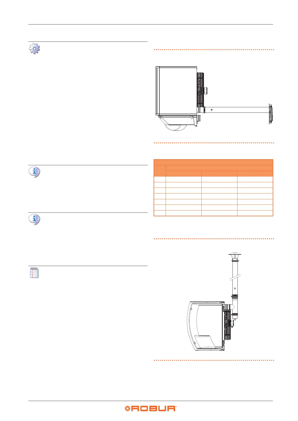
3.3.3.2 B23 type installation with roof ue gas exhaust
pipe
Figure3.2 B23 type installation with Ø 80 roof ue gas exhaust
pipe
A Right side view
A