Heating engineer
32
3
Table3.8 C33 type maximum allowed length with 100/150 roof
coaxial terminal
Indicative maximum lengths (m)
Air pipe Flue gas exhaust pipe
Ø 80 Ø 100 Ø 80 Ø 100
R15 30 30 30 30
R20 30 30 30 30
R30 19 30 19 30
R40 14 30 14 30
R50 5 21 5 21
R60 1 10 1 10
R80 - 1 - 1
Table3.9 C33 type maximum allowed length with 130/210 roof
coaxial terminal
Indicative maximum lengths (m)
Air pipe Flue gas exhaust pipe
Ø 80 Ø 110 Ø 130 Ø 80 Ø 110 Ø 130
R15 30 30 30 30 30 30
R20 30 30 30 30 30 30
R30 21 30 30 21 30 30
R40 15 30 30 15 30 30
R50 7 30 30 7 30 30
R60 3 26 30 3 26 30
R80 2 21 30 2 21 30
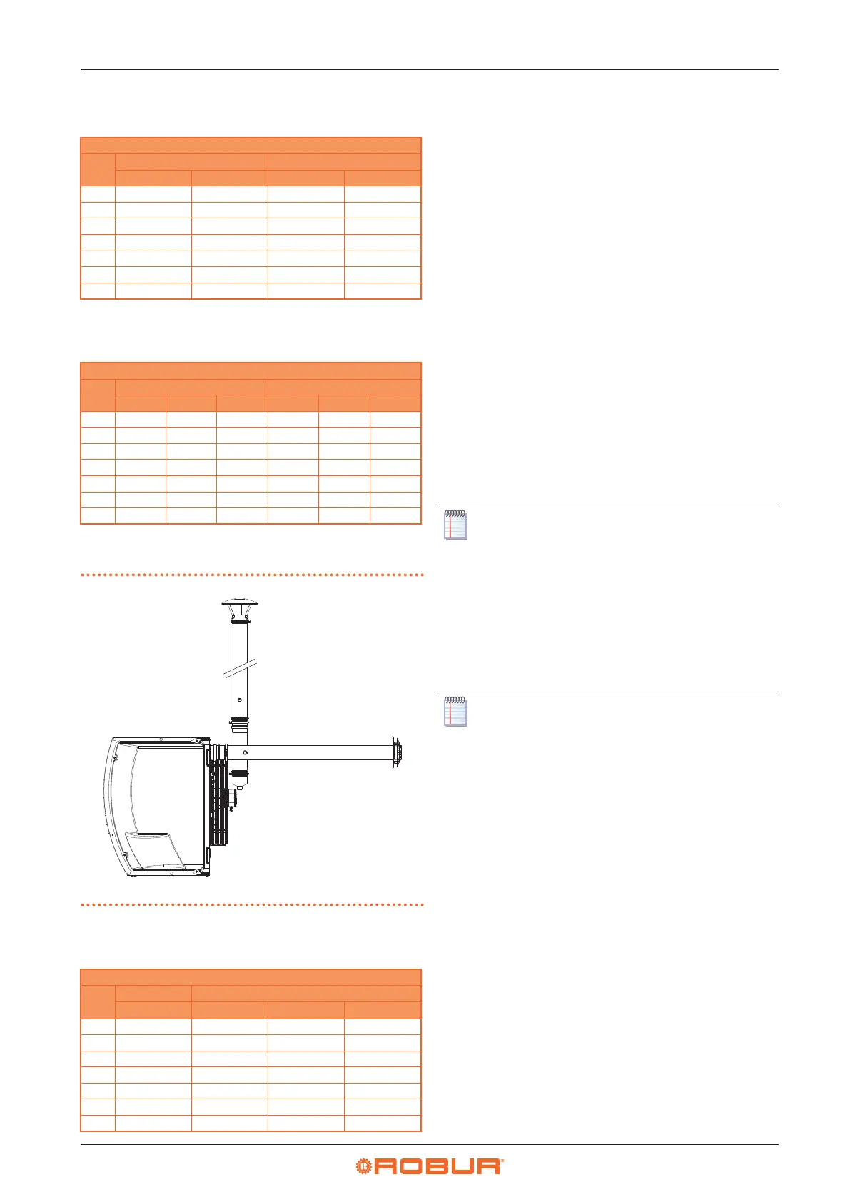
3.3.3.6 C53 type installation with separate ducts
Figure3.6 C53 type installation with Ø 80 separate ducts
A Right side view
A
Table3.10 C53 type maximum allowed length with separate
ducts
Indicative maximum lengths (m)
Air pipe Flue gas exhaust pipe
Ø 80 Ø 100 Ø 110
R15 1 30 30 30
R20 1 30 30 30
R30 1 30 30 30
R40 1 24 30 30
R50 1 12 30 30
R60 1 7 29 30
R80 1 6 26 30
3.3.4 Sizing and installing combustion air/
exhaust fumes ducts
In order to dimension the duct system, the total pressure
drop of the system must be calculated.
The total allowed pressure drop in the ue gas exhaust
system depends on the unit model (Table 3.11
p.33
).
The pressure drops of the ue and air pipes available as
Robur optional are shown in Table 3.12
p.33
.
Table 3.13
p.33
shows the pressure drops for Ø 100 ue
and air pipes in aluminium, available on the market.
The pressure drops of the coaxial pipes available as Robur
optional are shown in Table 3.14
p.33
.
Resistance from the separate terminals are negligible
since they are very low.
When designing, it must be checked that the total pres-
sure drop of the piping system is lower than the maximum
pressure drop allowed for the unit (Table 3.11
p.33
). An
example of how to calculate pressure drops is given in
Paragraph 3.3.5
p.34
.
The maximum lengths of air and ue gas exhaust pipes,
depending on the type of installation, are shown in tables
under the installation type gures, described in Paragraph
3.3.3
p.30
.
The above lengths are intended to be approxi-
mate values for standard installations where the
air and ue gas exhaust ducts follow linear paths
as shown in the respective gures. Otherwise, you
must proceed with the calculation of the pressure
drop (Paragraph 3.3.5
p. 34
): installation will be
permitted if the total pressure drop is lower than
the maximum admissible pressure drop (Table
3.11
p.33
).
The Ø 80, 110 and 130 pipes available as Robur op-
tional are made of stainless steel, while the Ø 100
adapters available as Robur optional are made of
aluminium.