Heating engineer
Installation, use and maintenance manual – Next-R
29
3
3.2.2 Mandatory shut-o valve
▶
Provide a gas shut-o valve (manual) on the gas supply
line, next to the appliance, to isolate it when required.
▶
Provide a three-piece pipe union.
▶
Perform connection in compliance with applicable
regulations.
3.2.3 Gas pipes sizing
The gas pipes must not cause excessive pressure drops
and, consequently, insucient gas pressure for the
appliance.
3.2.4 Supply gas pressure
This appliance is equipped for a maximum gas
supply pressure of 50 mbar.
The appliance's gas supply pressure, both static and dy-
namic, must comply with Table 3.1
p.29
, with tolerance
± 15%.
Non compliant gas pressure (Table 3.1
p. 29
)
may damage the appliance and be hazardous.
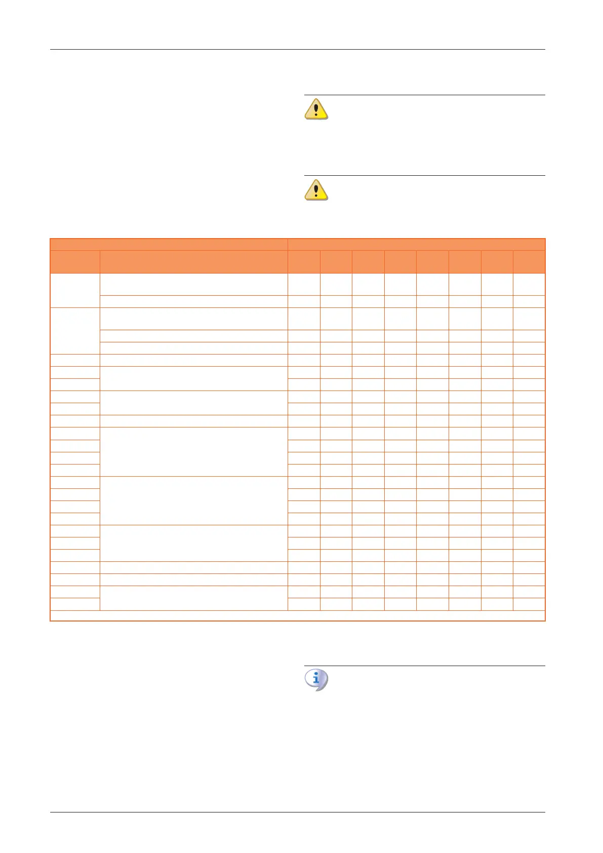
Table3.1 Network gas pressure
Gas supply pressure [mbar]
Product
category
Countries of destination G20 G25 G25.1 G25.3 G2.350 G27 G30 G31
II
2H3B/P
AL, BG, CH, CY, CZ, DK, EE, FI, GR, HR, IT, LT, LV, MK, NO,
RO, SE, SI, SK, TR
20 30 30
AT, CH 20 50 50
II
2H3P
AL, BG, CH, CZ, ES, GB, GR, HR, IE, IT, LT, LV, MK, PT, SI,
SK, TR
20 37
RO 20 30
AT 20 50
II
2ELL3B/P
DE 20 20 50 50
II
2Esi3P
FR
20 25 37
II
2Er3P
20 25 37
II
2H3B/P
HU
25 30 30
II
2HS3B/P
25 25 30 30
II
2E3P
LU 20 50
II
2L3B/P
NL
25 30 30
II
2L3P
25 37
II
2EK3B/P
20 25 30 30
II
2EK3P
20 25 30
II
2E3B/P
PL
20 37 37
I
2E
20
II
2ELwLs3B/P
20 13 20 37 37
II
2ELwLs3P
20 13 20 37
I
2E(R)
BE
20 25
I
2E(S)
20 25
I
3P
37
I
3P
IS 30
I
2H
LV 20
I
3B/P
MT
30 30
I
3B
30
The appliance gas supply pressure, both static and dynamic, must comply with the values in the Table, with a tolerance of ± 15%.
3.2.5 Vertical pipes and condensate
▶
Vertical gas pipes must be tted with siphon and dis-
charge of the condensate that may form inside the
pipe.
▶
If necessary, insulate the piping.
3.2.6 LPG pressure reducers
With LPG the following must be installed:
▶
A rst stage pressure reducer, close to the liquid gas
tank.
▶
A second stage pressure reducer, close to the appli-
ance.
3.3 COMBUSTION PRODUCTS EXHAUST
Compliance with standards
The appliance is approved for connection to a
combustion products exhaust duct for the types
shown in Table 1.2
p.23
.
3.3.1 Flue gas exhaust connection
▶
Ø 80 mm with gasket, on the rear, at the top (see di-
mensional diagrams, Paragraph 1.2
p.8
).
For all models, it is possible to move the fumes gas outlet