Electrical installer
36
4
5 on dimensional diagrams, Paragraph 1.2
p.8
).
3. Insert cables through cable gland (detail 3 on dimen-
sional diagrams, Paragraph 1.2
p. 8
). PG9 cable
glands are suitable for cables with diameters from 3,5
to 8 mm. PG13.5 cable glands are suitable for cables
with diameters from 6 to 12 mm.
4. Identify the appropriate connection terminals.
5. Make the connections.
6. Close the thermoformed door.
4.3 ELECTRICAL POWER SUPPLY
4.3.1 Power supply line
Provide (by the installer) a protected single phase line
(230 V 1-N 50 Hz) with:
▶
H05 VVF 3x1,5 mm
2
type cable with a maximum exter-
nal diameter of 12 mm.
▶
Bipolar disconnector with minimum contact opening
of 3 mm.
How to connect the power supply
To connect the three-pole power supply cable:
1. Access the connection terminal block according to
Procedure 4.2
p.35
.
2. Connect the three wires to the terminal block as shown
in Figure 4.1
p.36
.
3. Provide the earth lead-in wire longer than live ones
(last to be torn in the event of accidental pulling).
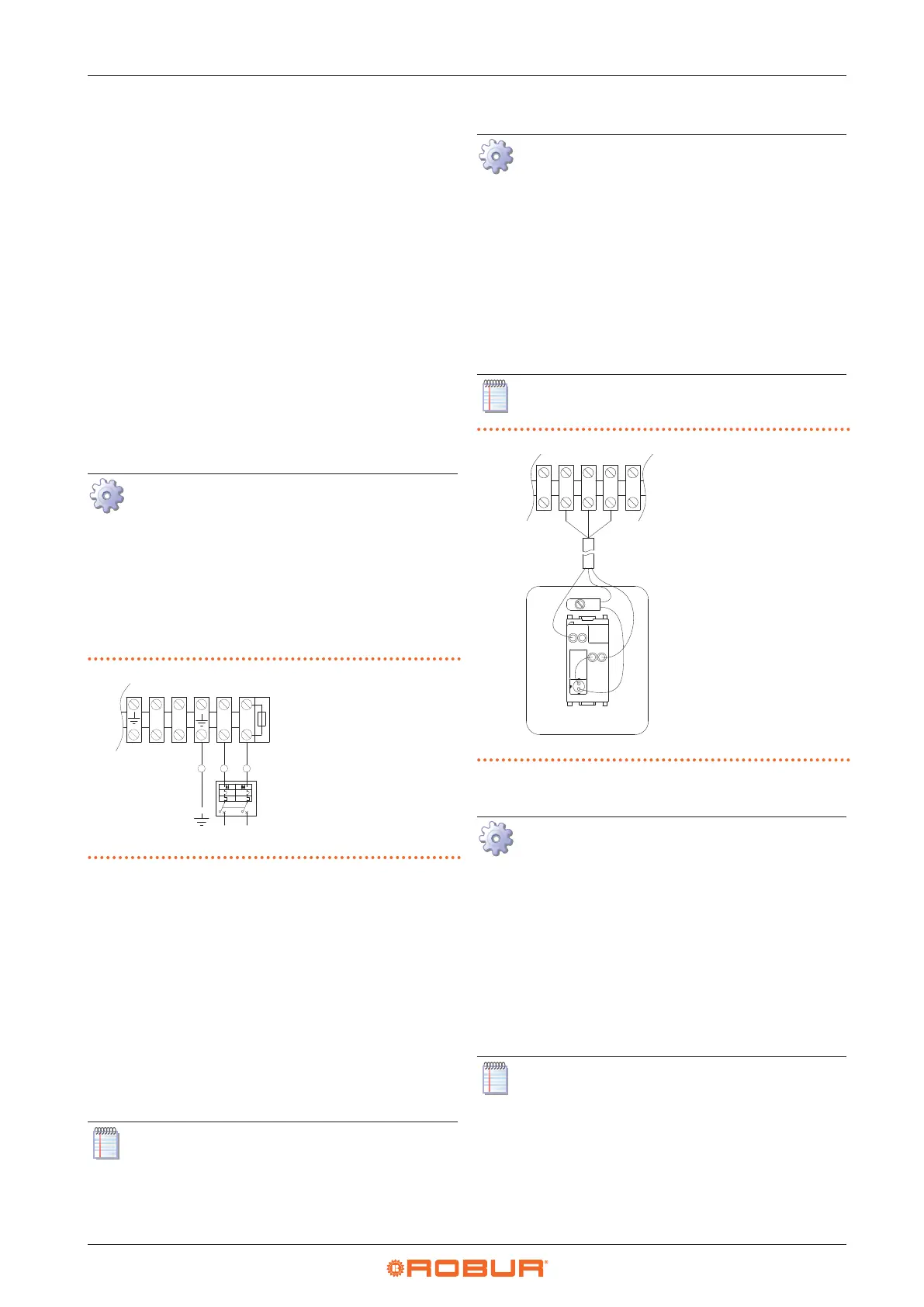
Figure4.1 Appliance connection to the mains power supply
L Phase
N Neutral
Components NOT
SUPPLIED:
GS Two-pole switch
N L
V2L
V1N
N L
GS
4.4 CONTROL SYSTEM
Six separate adjustment systems are provided, each with
specic features, components and diagrams:
1. OCDS012 1-key basic control
2. OCTR000 2-key basic control
3. OTRG005 thermoregulator
4. OCDS008 digital chronothermostat (in association
with OTRG005 thermoregulator)
5. Genius software for remote management of gas unit
heaters (in association with OTRG005 thermoregulator)
6. External request
Control systems 3, 4 and 5 manage automatically
the power modulation of the unit on two power
levels.
4.4.1 OCDS012 1-key basic control
How to connect the OCDS012 1-key basic con-
trol
The control must be installed on the wall in a suita-
ble position, using expansion screws.
1. Access the connection terminal block according to
Procedure 4.2
p.35
.
2. Use 3x1 mm
2
cable for connection.
3. Connect the wires to the terminal block as shown in
Figure 4.2
p.36
.
4. For further information refer to the instruction sheet
supplied with the OCDS012 optional.
The cable may not be longer than 20 metres.
Figure4.2 1-key basic control connection
L1 Lockout lamp
P1 Reset button
3 5 6 7
Z92
L1
P1
5
6
7
L
1
4.4.2 OCTR000 2-key basic control
How to connect OCTR000 2-key basic control
The control must be installed on the wall in a suita-
ble position, using expansion screws.
1. Access the connection terminal block according to
Procedure 4.2
p.35
.
2. Use FRORR 6x1 mm² cable (available as OCVO015 op-
tional, with 5 m length).
3. Connect the wires to the terminal block as shown in
Figure 4.3
p.37
.
4. For further information refer to the instruction sheet
supplied with the OCTR000 optional.
The cable may not be longer than 20 metres.