Electrical installer
Installation, use and maintenance manual – Next-R
37
4
Figure4.3 2-key basic control connection
L1 Lockout lamp
P1 Reset button
Z1 Summer/winter
switch
3 5 6 7
Z92
1 2
Z1 P1
7
5
63
1
2
1
L
2
L1
L
1
4.4.3 OTRG005 thermoregulator
How to connect OTRG005 thermoregulator
The thermoregulator must be installed on the wall
in a suitable position, using expansion screws.
Connection of the thermoregulator is made on the
wiring terminal block located in the electrical pan-
el inside the unit.
To connect OTRG005 thermoregulator:
1. Access the connection terminal block according to
Procedure 4.2
p.35
.
2. Remove 27 and 28 temporary jumpers on the terminal
block (Paragraph 1.4
p.20
).
3. Use FRORR 7x1 mm² cable (available as OCVO015 op-
tional, with 5 m length).
4. Make electrical connections as described in Figure
4.4
p.37
and in Table 4.1
p.37
.
5. For further information refer to the instruction sheet
supplied with the OTRG005 optional.
The cable may not be longer than 10 metres.
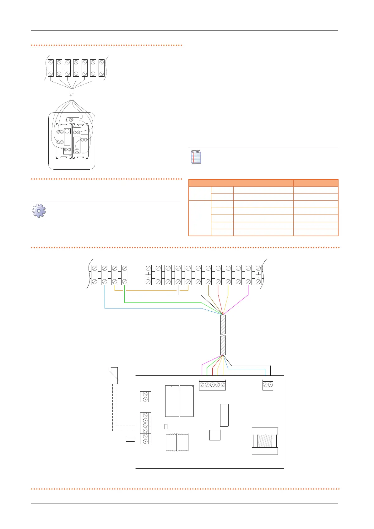
Table4.1 OTRG005 thermoregulator connection
OTRG005 thermoregulator Next-R
J1
1 Line 1
2 Neutral N
J2
1 OF 5
2 RES 7
3 LF 6
4 FAN C
5 REQ Z91
Figure4.4 OTRG005 thermoregulator connection
A OTRG005 thermoregulator
B Room temperature probe (supplied)
C Gas unit heater terminal block
D J6 electrical bridge
1
S2
S1
2 3 5 6 7
NC
CNL
28
Z92
Z91
J1
J2
2
1
J3
J4
J5
J6
1
2
1
2
3
4
5
2
1
2
1
2
1
JP
B
D
A
C