Features and technical data
20
1
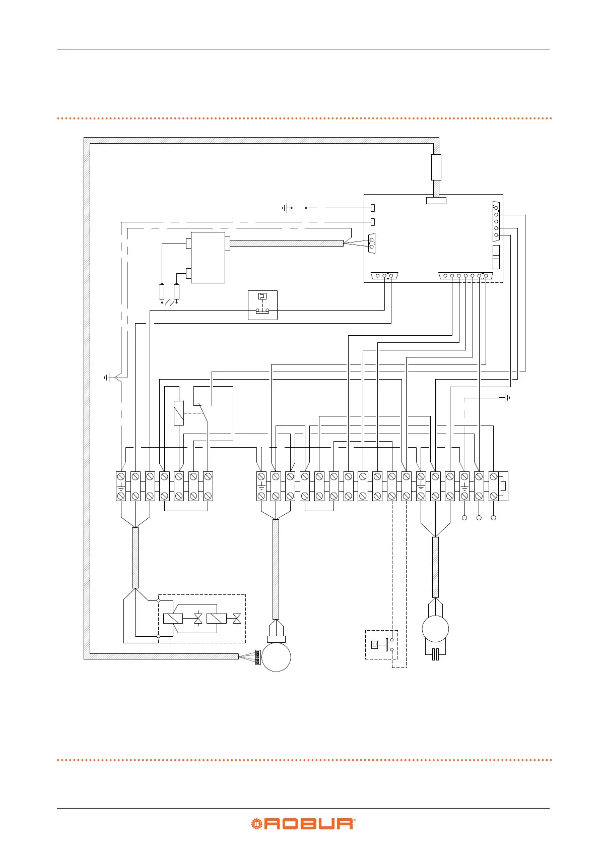
1.4 ELECTRICAL WIRING DIAGRAM
1.4.1 R15/R20
Figure1.14 Electrical wiring diagram
CV Fan condenser
K1 Internal modulation relay
M1 Limit thermostat
M4 Controller for ignition, adjustment and ame control
Q1 Gas valve
RP7 Ignition electrodes
RP8 Flame sensor
S Blower
TR Ignition transformer
V1 Fan
Z9 External request (not supplied)
27 Power level control contact
28 Winter mode activation contact
Ground
T2
T1
M1
K1
Ground
bracket
T3
T5
T4
10
2
6
1
2
3
4
5
6
7
FUSE 6.3A
13
14
15
J2
89
11
10
20
1
S2
S1
2 3 5 6 7 N L
NC
CNL
Z92
Z91
V2L
V1N
Q1L
Q1N
T6
230V~50Hz
CV
L
N
S
~
Q1
V1
~
3
4
12 2 4
3
6 10 1
1
1
3
3 39
9
2 27 811 4
RP8
12
J5
J3
J1
J7
J6
M4
J8
FUSE
4AF
21
TR
RP7
27
28
Z9