Normal operation
46
6
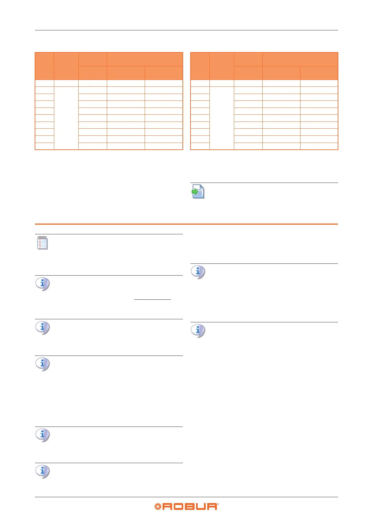
Table5.6 R60 gas valve setting table
Gas
Gas
network
pressure
Oset
pressure
CO
2
percentage in fumes
nominal
Minimal heat
input
Nominal heat
input
Type mbar Pa % %
G20
See Table
3.1
p.29
-10 8,9 9,4
G25 -10 8,7 9,0
G25.1 -10 10,5 10,9
G25.3 -10 8,8 9,2
G27 -10 9,2 9,4
G2.350 -10 9,1 9,4
G30 -10 10,4 10,6
G31 -10 10,1 10,4
LPG -10 9,8 10,2
A tolerance of ±0,3% is applied to all values of CO
2
percentage in fumes.
Table5.7 R80 gas valve setting table
Gas
Gas
network
pressure
Oset
pressure
CO
2
percentage in fumes
nominal
Minimal heat
input
Nominal heat
input
Type mbar Pa % %
G20
See Table
3.1
p.29
-10 9,1 9,3
G25 -10 8,7 9,2
G25.1 -10 10,5 10,9
G25.3 -10 8,9 9,3
G27 -10 8,8 9,2
G2.350 - - -
G30 -10 10,2 10,5
G31 -10 9,9 10,2
LPG -10 9,7 10,1
A tolerance of ±0,3% is applied to all values of CO
2
percentage in fumes.
5.3 GAS CHANGEOVER
For gas change instructions, refer to the rele-
vant documentation.
6 NORMAL OPERATION
This section is for the end user.
6.1 WARNINGS
General warnings
Prior to using the appliance carefully read the
warnings in Chapter III.1
p. 4
, providing impor-
tant information on regulations and on safety.
First startup by TAC
First start-up may exclusively be carried out by a
Robur TAC (Chapter 5
p.42
).
Never power the appliance o while it is run-
ning
NEVER power the appliance o while it is running
(except in the event of danger, Chapter III.1
p. 4
),
since the appliance or system might be damaged.
6.2 SWITCH ON AND OFF
Routine switching on/o
The appliance may exclusively be switched on/o
by means of the suitably provided control device.
Do not switch on/o with the power supply
switch
Do not switch the appliance on/o with the power
supply switch. This may be harmful and dangerous
for the appliance and for the system.
Checks before switching on
Before switching on the appliance, ensue that:
gas valve open
appliance electrical power supply (main switch ON)
connection and any necessary power supply of the
control device
After a long period of unit inactivity or at the rst
start-up, it may be necessary to repeat the ignition
operation due to the presence of air in the gas
piping.
6.2.1 OCDS012 1-key basic control
Space heating activation
1. Ensure that contact 1-3 is closed by the factory in-
stalled temporary jumper. If a summer/winter selector
switch (Paragraph 4.4.6.2
p. 39
) has been installed,
ensure that the selector switch is in the "winter" posi-
tion (contact 1-3 closed).
2. Switch on Z9 contact using the provided control de-
vice (thermostat, chronothermostat or voltage-free
contact).
3. After the purge time (around 40 seconds), the gas so-
lenoid valve opens and the burner ignites.
4. When the ame is detected, the control box keeps the
gas valve open.
5. Otherwise, the control unit will try the ignition again
3 times, after the appropriate purge time. If the ame