First start-up
Installation, use and maintenance manual – Next-R
45
5
Table5.5 R50 gas valve setting table
Gas
Gas network
pressure
Screw pre-adjustment Oset pressure CO
2
percentage in fumes
Throttle Oset nominal Minimal heat input Nominal heat input
Type mbar
turns turns
Pa % %
G20
See Table
3.1
p.29
-14 -3 ¾ -10 8,6 9,2
G25 full open -3 ¾ -10 8,5 9,0
G25.1 -16 ¾ -3 ¾ -10 10,0 10,5
G25.3 full open -3 ¾ -10 8,6 9,2
G27 -16 -3 ¾ -10 8,6 9,0
G2.350 full open -3 ¾ -10 8,6 9,1
G30 -4 ½ -3 ¾ -10 9,9 10,5
G31 full open -3 ¾ -10 9,5 10,0
LPG -14 ¼ -3 ¾ -10 9,7 10,3
A tolerance of ±0,3% is applied to all values of CO
2
percentage in fumes.
5.2.2 R60/R80
Figure 5.2
p.45
1. If the appliance is running, switch it o with the appli-
cable control system.
2. Connect a pressure gauge to oset pressure tting (A),
after having rst removed or loosed the sealing screw.
3. Open contact 27 (L-C terminals), or act on the power
level control device to force gas unit heater operation
at minimum power.
4. Switch on the gas unit heater using the provided con-
trol device.
5. After about 2 minutes, the combustion control at min-
imum power can be carried out.
6. Turn the oset adjustment screw until the nominal
oset pressure value shown in the following Tables is
obtained, with a tolerance of ±1 Pa.
7. Ensure the CO
2
value is between values indicated in
column "Minimal heat input" of the following Tables,
depending on the model and the gas type used.
Otherwise set CO
2
percentage reading by acting on
the oset adjustment screw.
Check the burner, which must not have reddened
areas.
8. Disconnect the pressure gauge and tighten the seal-
ing screw of the pressure intake (A).
9. Close contact 27 (L-C terminals), or act on the power
level control device to force gas unit heater operation
at maximum power.
10. After about 2 minutes, the combustion control at max-
imum power can be carried out.
11. Ensure the CO
2
value is between values indicated in
column "Nominal heat input" of the following Tables,
depending on the model and the gas type used.
If the check is successful:
12. Set contact 27 (L-C terminals) back in its original posi-
tion or stop manual forcing of the power level.
If the check is not successful:
13. Repeat steps 3 to 7 (excluding step 6) to reactivate the
minimum power operation; check again and, if neces-
sary, correct the CO
2
value in such conditions by actu-
ating the oset adjustment screw.
14. Repeat step 12 to complete the procedure.
Check that the static and dynamic supply gas
pressure values, with the gas unit heater running
at maximum power, correspond to what is shown
in Table 3.1
p. 29
(with low supply gas pressure
values the CO
2
value will also be at minimum
values).
If the control systems are designed so that the
gas unit heater activation request depends on the
room temperature, the gas unit heater may not
start because the room temperature is already at
requested setpoint. In this case, set the forcing for
manual activation on the control system, or close
contact Z9 (Z91-Z92 terminals) manually.
Remember to set contact 27 (L-C terminals) back
in its original position or stop manual forcing of
the power level after the conclusion of checking
operations.
If it has been set, remember to disable the
forcing for manual activation on the control
system, or manual close of contact Z9 (Z91-Z92
terminals).
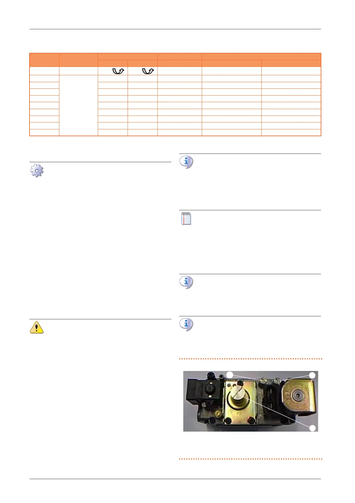
Figure5.2 Gas valve
A Oset pressure intake
B Gas mains pressure intake
C Oset adjustment screw
C
B