Heating engineer
28
3
mounting brackets, as they must be suspended from the
ceiling of the heated room.
The gas unit heater is equipped, on the fan side, with ap-
propriate vertical suspension brackets, to which the gas
unit heater supports can be connected.
Do not use other systems to hang the gas unit
heater than the provided brackets.
The R15 and R20 gas unit heaters are not equipped
with vertical suspension brackets, as the installa-
tion with vertical downow is carried out by means
of the revolving bracket OSTF020 (available as an
optional, Paragraph 2.5.4
p.28
).
Figure2.5 Under ceiling support brackets
A Vertical suspension brackets
A
A
A
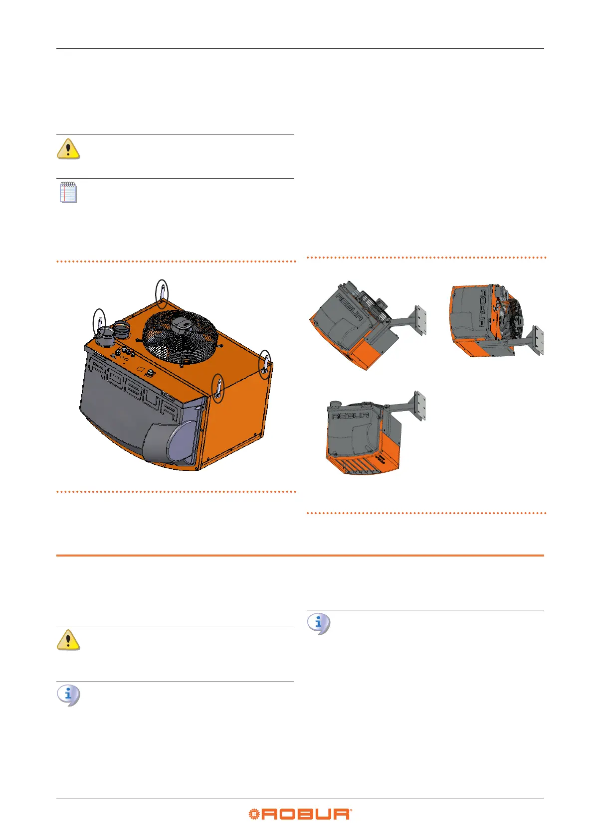
2.5.4 OSTF020 revolving wall support bracket
(R15, R20 models)
For R15 and R20 gas unit heaters, the OSTF020 revolving
bracket (available as an optional) allows the gas unit heat-
er to be oriented both horizontally, or inclined by 45°, or
with vertical downow (inclined by 90°), always using the
same bracket.
The bracket must in any case be positioned on the wall,
even in the case of vertical downow (it is not possible
to suspend the gas unit heater in this case, as it is not
equipped with vertical suspension brackets).
The bracket is supplied with bolts and the rear support
plate.
For mounting instructions of the bracket, refer to the rele-
vant instruction sheet.
Figure2.6 OSTF020 bracket positions
A Bracket in horizontal position
(0°)
B Bracket at 45°
C Bracket at 90°
A
C
B
3 HEATING ENGINEER
3.1 WARNINGS
3.1.1 General warnings
Read the warnings in Chapter III.1
p. 4
, pro-
viding important information on regulations and
on safety.
Compliance with installation standards
Installation must comply with applicable regula-
tions in force, based on the installation Country
and site, in matters of safety, design, implementa-
tion and maintenance of:
heating systems
gas systems
ue gas exhaust
ue gas condensate discharge
Installation must also comply with the manufactur-
er's provisions.
3.2 FUEL GAS SUPPLY
3.2.1 Gas connection
▶
3/4" M (R15, R20, R30, R40, R50 models)
▶
3/4" F (R60, R80 models)
on the rear, to the left (see dimensional diagrams,
Paragraph 1.2
p.8
).
▶
Install an anti-vibration connection between the ap-
pliance and the gas piping.