Electrical installer
Installation, use and maintenance manual – Next-R
39
4
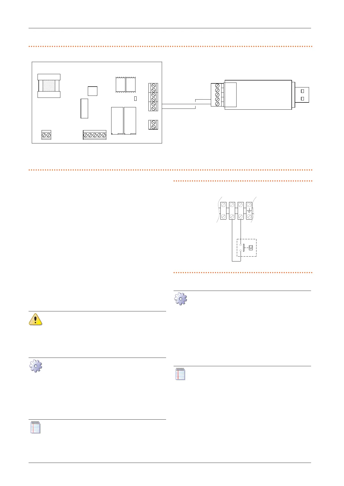
Figure4.6 USB/RS485 converter connection
A A signal
B B signal
C OTRG005 thermoregulator
D USB/RS485 converter
1
2
J1
1
J2
1
2
J3
J4
J5
J6
JP
1
2
1
2
1
2
2
3
4
5
A
B
D
4.4.6 External request
Depending on the required operation, it is required to
arrange:
▶
Request device (e.g. thermostat, timer, switch, ...)
equipped with a voltage-free NO contact, used for
managing start/stop of the gas unit heater.
▶
Request device (switch) equipped with a changeover
contact, for managing winter/summer mode opera-
tion.
▶
Request device (e.g. button) equipped with a volt-
age-free NO contact, used for managing the two gas
unit heater power levels. Through the use of a 2-step
thermostat or chronothermostat, it is possible to unify
the gas unit heater start/stop management with the
two power levels management.
For details on the position and possible presence of tem-
porary jumpers on terminals of the unit terminal block,
refer to the wiring diagrams in Paragraph 1.4
p.20
.
All the contacts for external requests of the ter-
minal block in the electrical panel inside the
unit have a 230 V voltage applied to the relative
terminals.
4.4.6.1 Gas unit heater start/stop management
How to connect the external request for gas
unit heater start/stop management
1. Access the electrical board of the appliance according
to the Procedure 4.2
p.35
.
2. Connect the voltage-free contact of the external re-
quest, using a 2x1 mm² cable, to Z9-Z9 terminals of the
terminal block, as shown in Figure 4.7
p.39
.
The cable may not be longer than 20 metres.
Figure4.7 Connection of external request for gas unit heater
start/stop management
Z9 External request (e.g. thermostat, timer, switch, ...)
7
Z92
Z91
4.4.6.2 Summer/winter mode management
How to connect the external request for
summer/winter mode management
1. Access the electrical board of the appliance according
to the Procedure 4.2
p.35
.
2. Remove the 28 temporary jumper between 1-3 termi-
nals on the internal terminal block.
3. Connect the voltage-free contact of the external re-
quest, using a 3x1 mm² cable, to 1, 2, 3 terminals of the
terminal block, as shown in Figure 4.8
p.40
.
The cable may not be longer than 20 metres.