Electrical installer
40
4
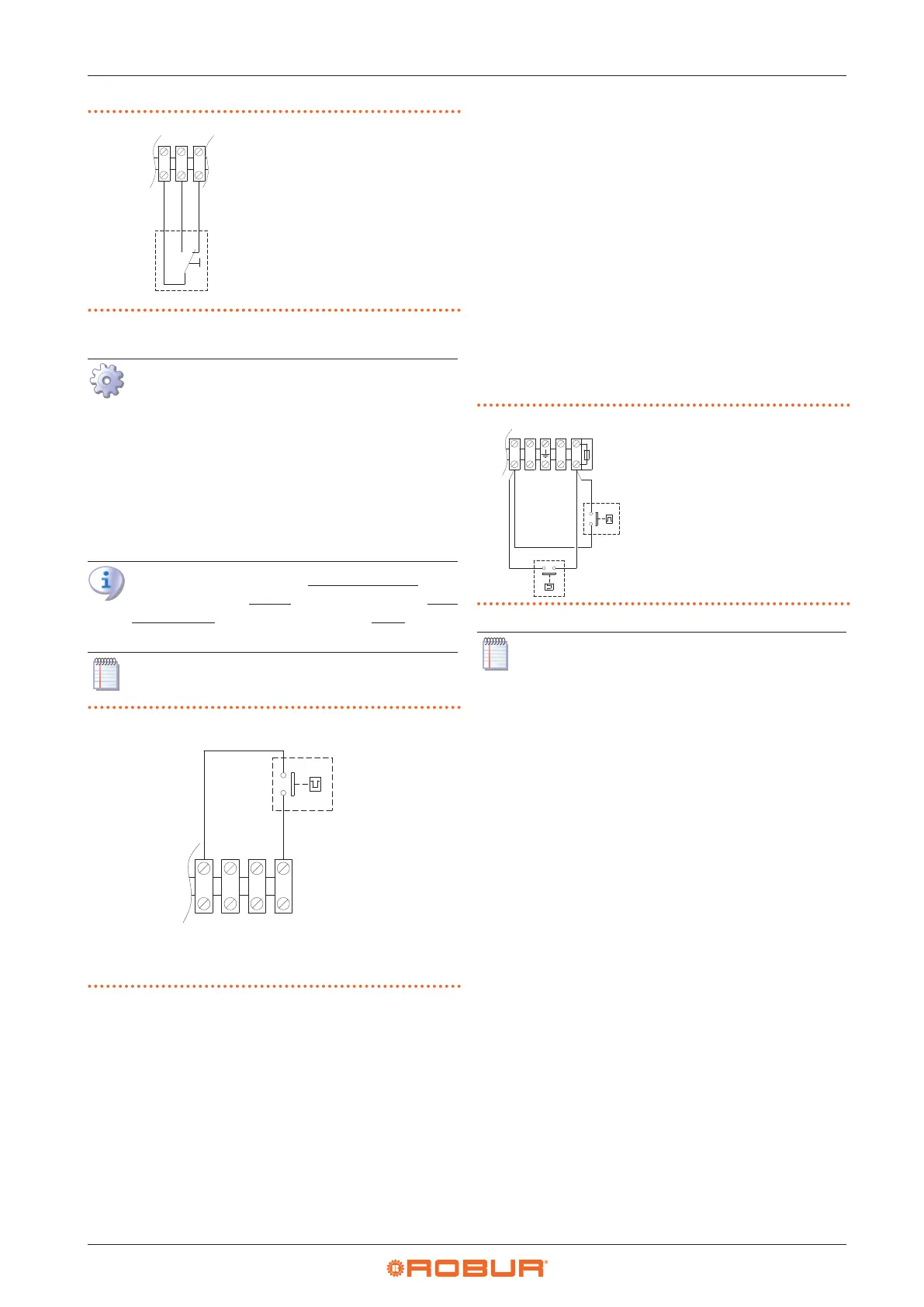
Figure4.8 Summer/winter switch connection
Z1 Summer/winter
switch
1 2 3
4.4.6.3 Power level control
How to connect the external request for gas
unit heater power level management
1. Access the electrical board of the appliance according
to the Procedure 4.2
p.35
.
2. Remove the 27 temporary jumper between L-C termi-
nals on the internal terminal block.
3. Connect the voltage-free contact of the external re-
quest, using a 2x1 mm² cable, to L-C terminals of the
terminal block, as shown in Figure 4.9
p.40
.
Gas unit heater operates at maximum power when
the L-C contact is closed, while it operates at min-
imum power when the L-C contact is open.
The cable may not be longer than 20 metres.
Figure4.9 Gas unit heater power level selector switch
connection
A Gas unit heater power level selector switch
• Closed contact: gas unit heater at maximum power
• Open contact: gas unit heater at minimum power
NC
CNL
4.4.6.4 2-step thermostat
With a 2-step thermostat (or chronothermostat) it is possi-
ble to combine the functions of start/stop and power lev-
el management of the gas unit heater in a single control.
Connections must be made according to the wiring
diagram of the specic thermostat used (refer to the
thermostat manufacturer's documentation), respecting
the specications in Paragraph 4.4.6.1
p. 39
in relation
to the gas unit heater start/stop request and in Paragraph
4.4.6.3
p.40
in relation to the gas unit heater two power
level management.
4.4.6.5 Operation as destratier
For vertical downow gas unit heaters only, it is possible
to use a thermostat, suitably positioned, to allow the op-
eration of the appliance's fan only (with the burner o),
for thermal destratication.
This way, if the temperature measured by the thermostat
in its installation point is higher than the threshold set on
the thermostat itself, it will give the request, to the fan on-
ly, which will push the warm air ow down again.
Thermostat connection is shown in Figure 4.10
p.40
.
Figure4.10 Destratication thermostat connection
A Destratication thermostat (to
be provided)
M2 Fan thermostat (provided on
the gas unit heater)
N L
FUSE 6.3A
V2L
V1N
1
9
The gas unit heater fan will be activated each time
it receives the request from the destratication
thermostat, regardless of any other request.
4.4.6.6 Control of multiple gas unit heaters with a
single external request
Through a suitable connection to the terminals described
above, it is possible to manage the specic function on
more than one gas unit heater using a single external
request.
In the case of centralized management of multiple gas
unit heaters start/stop, advice given is to use:
▶
OCDS008 digital chronothermostat (described in
Paragraph 1.6.5
p.23
), up to 10 gas unit heaters.
▶
OSWR000 Genius software (described in Paragraph
1.6.6
p.23
), up to 100 gas unit heaters.
If you do not want to use these solutions, the central-
ized management of start/stop can be done as described
in Figure 4.11
p. 41
, using a programmable timer and
several room thermostats. The room thermostats serving
each gas unit heater allow the gas unit heater to be ac-
tivated only when the specic zone actually needs heat,
avoiding wastage of energy. The programmable timer
allows subordinating the gas unit heater activation, even
if requested by the room thermostat, to a centralized
request.