Heating engineer
Installation, use and maintenance manual – Next-R
33
3
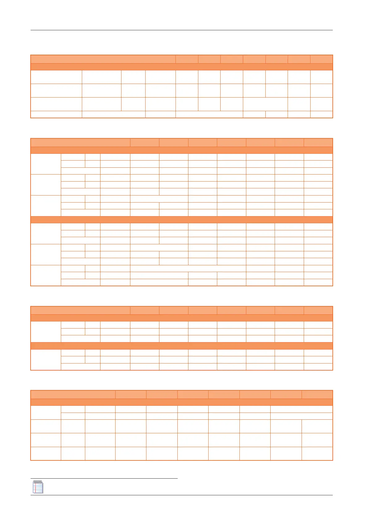
Table3.11 Data for the calculation of the air/fumes system with pipes found on the market
R15 R20 R30 R40 R50 R60 R80
Installation data
Flue temperature
Nominal heat
input
G20 °C 210,0 200,0 218,0 195,0 196,0 180,0 220,0
Fumes ow rate
Nominal heat
input
G20 kg/h 27 35 48 65 83 116 142
CO
2
percentage in fumes
Nominal heat
input
G20 % 9,3 9,2 9,0 9,2 9,4 9,3
Flue gas exhaust residual head Pa 70 90 80 100 130
Table3.12 Data for the calculation of the air/fumes system with Ø 80/110/130 pipes available as optional
R15 R20 R30 R40 R50 R60 R80
Flue gas exhaust pressure drop
Ø 80 mm
Pipe 1 m Pa 0,7 1,0 1,9 3,2 5,0 9,2 13,4
Elbow 90° Pa 0,9 1,5 2,8 5,0 8,0 15,4 22,7
Tee Pa 2,0 3,1 5,6 9,6 15,0 27,7 40,3
Ø 110 mm
Pipe 1 m Pa 0,1 0,2 0,4 0,7 1,1 1,9 2,8
Elbow 90° Pa 0,3 0,4 0,8 1,4 2,2 4,3 6,3
Tee Pa 0,4 0,7 1,2 2,1 3,2 5,8 8,4
Ø 130 mm
Pipe 1 m Pa 0,1 0,2 0,3 0,5 0,9 1,2
Elbow 90° Pa 0,1 0,2 0,4 0,7 1,1 2,2 3,2
Tee Pa 0,2 0,3 0,5 0,9 1,4 2,6 3,7
Air intake pressure drop
Ø 80 mm
Pipe 1 m Pa 0,3 0,5 0,9 1,5 2,4 4,4 6,3
Elbow 90° Pa 0,4 0,7 1,2 2,2 3,6 6,9 10,2
Tee Pa 1,0 1,5 2,6 4,5 7,1 13,1 19,0
Ø 110 mm
Pipe 1 m Pa 0,1 0,2 0,3 0,5 0,9 1,3
Elbow 90° Pa 0,1 0,2 0,3 0,6 1,0 1,9 2,8
Tee Pa 0,2 0,3 0,6 1,0 1,5 2,7 3,9
Ø 130 mm
Pipe 1 m Pa 0,1 0,2 0,4 0,6
Elbow 90° Pa 0,1 0,2 0,3 0,5 1,0 1,4
Tee Pa 0,1 0,3 0,4 0,7 1,2 1,8
Table3.13 Data for the calculation of the air/fumes system with Ø 100 pipes
R15 R20 R30 R40 R50 R60 R80
Flue gas exhaust pressure drop
Ø 100 mm
Pipe 1 m Pa 0,2 0,4 0,6 1,1 1,6 3,0 4,3
Elbow 90° Pa 0,4 0,6 1,1 2,0 3,2 6,1 9,0
Tee Pa 0,7 1,1 1,9 3,2 4,9 9,0 12,9
Air intake pressure drop
Ø 100 mm
Pipe 1 m Pa 0,1 0,2 0,3 0,5 0,8 1,4 2,0
Elbow 90° Pa 0,2 0,3 0,5 0,9 1,4 2,7 4,0
Tee Pa 0,3 0,5 0,9 1,5 2,3 4,3 6,1
Table3.14 Data for the calculation of the air/fumes system with coaxial pipes available as optional
R15 R20 R30 R40 R50 R60 R80
Coaxial exhaust pipe pressure drop
Ø 80/125 mm
wall Pa 5,9 6,4 8,0 11,7 17,5 -
roof Pa 6,2 8,1 11,0 20,4 37,0 -
Ø 130/180
mm
wall (1) Pa 1,2 1,4 1,6 2,0 3,0 6,4 12,0
Ø 100/150
mm
roof Pa 2,6 3,3 9,0 12,0 19,0 38,6 70,0
Ø 130/210
mm
roof Pa 0,9 1,2 3,3 4,3 6,7 13,2 23,5
(1) Can be used only with OSTF009 support bracket
If horizontal ue gas exhaust pipes having lengths above 1 m are installed, the ue gas exhaust pipe