4 Rockwell Automation Publication 2198-IN021A-EN-P - June 2020
Kinetix 5300 Single-axis EtherNet/IP Servo Drives Installation Instructions
Connector Data
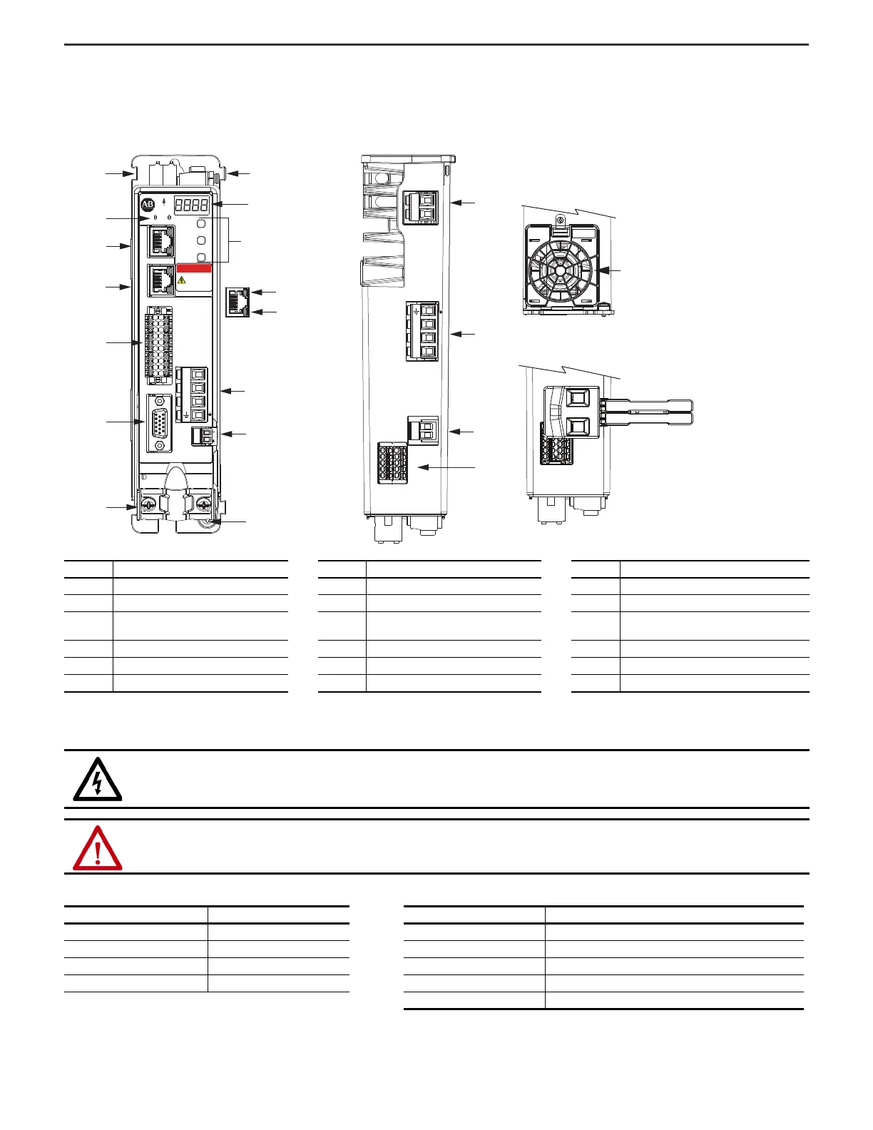
Use these illustrations to identify the Kinetix 5300 drive features and indicators.
Kinetix 5300 Drive Features and Indicators
These procedures assume that you have prepared your panel and understand how to bond your system. For installation instructions regarding equipment and accessories
not included here, refer to the instructions that came with those products.
Kinetix 5300 Drive Connectors
Item Description Item Description Item Description
1 Motor cable shield clamp 7 Zero-stack mounting tab/cutout 13 Motor brake connector
2 Motor feedback (MFB) connector 8 Four-character status display 14 Ground terminal
3
Digital inputs and auxiliary feedback
connector
9 Navigation pushbuttons 15 Shunt resistor connector
4 Ethernet (PORT1) RJ45 connector 10 Link speed status indicators 16 AC input power connector
5 Ethernet (PORT2) RJ45 connector 11 Link/Activity status indicators 17 24V control input power connector
6 Module and Network status indicators 12 Motor power connector 18 Safe torque-off (STO) connector
SHOCK HAZARD: To avoid hazard of electrical shock, perform all mounting and wiring of the Kinetix 5300 drive prior to applying power. Once power is
applied, connector terminals can have voltage present even when not in use.
ATTENTION: Plan the installation of your system so that you can perform all cutting, drilling, tapping, and welding with the system removed from the
enclosure. Because the system is of the open type construction, be careful to keep any metal debris from falling into it. Metal debris or other foreign
matter can become lodged in the circuitry and result in damage to components.
Description Connector Description Connector
AC input power 4-position plug, terminal screws Motor feedback (MFB) 15-position plug
24V control input power 2-position plug, terminal screws Brake power (MBRK) 2-position plug, terminal screws
Shunt power 2-position plug, terminal screws Digital inputs / Auxiliary feedback 20-position plug, spring terminals
Motor power 4-position plug, terminal screws Safe torque-off (STO) 10-position plugs, spring terminals, 2x (2 rows of 5 pins)
Ethernet communication ports RJ45 Ethernet
18
17
16
15
L3
L2
L1
1
8
2
3
11
4
5
9
10
14
6
7
13
12
L3L2
L1
24+
DC+ SH
24-
SB+
SB-
S1
SC
S2
7
2
1
2
1
MOD NET
MBRK
W
V
U
1
10
1
2
MFB
SELECT
BACK
NEXT
KINETIX
5300
DANGER
Electric shock
risk. Power
off and wait
5 minutes.
U
V
W
SB+
SB-
S1
SC
S2
Kinetix 5300 Drive, Front View
(2198-C1004-ERS drive is shown)
Kinetix 5300, Top View
(2198-C1004-ERS drive is shown)
Shared-bus 24V Input
Wiring Connector
Kinetix 5300, Bottom View
(frame 2 and 3 drives only)
Cooling Fan
 Loading...


