Rockwell Automation Publication 2198-IN021A-EN-P - June 2020 2
Kinetix 5300 Single-axis EtherNet/IP Servo Drives Installation Instructions
Before You Begin
Remove all packing material, wedges, and braces from within and around the components. After unpacking, check the item nameplate catalog number against the purchase
order.
The Kinetix 5300 servo drives include the following:
• Wiring-plug connector set for AC input power, 24V control input power, digital inputs/auxiliary feedback, motor power, motor brake, shunt (installed and wired to
the internal shunt), and safe torque-off (STO) connector. Spare shunt wiring plug for optional external shunt.
• Clamp spacer for motor shield clamp
• The frame 3 clamping plate, for cables too large to fit within the standard shield clamp
• These installation instructions, publication 2198-IN021
Mount the Kinetix 5300 Drive
Follow these steps to mount the drive in single-axis configurations.
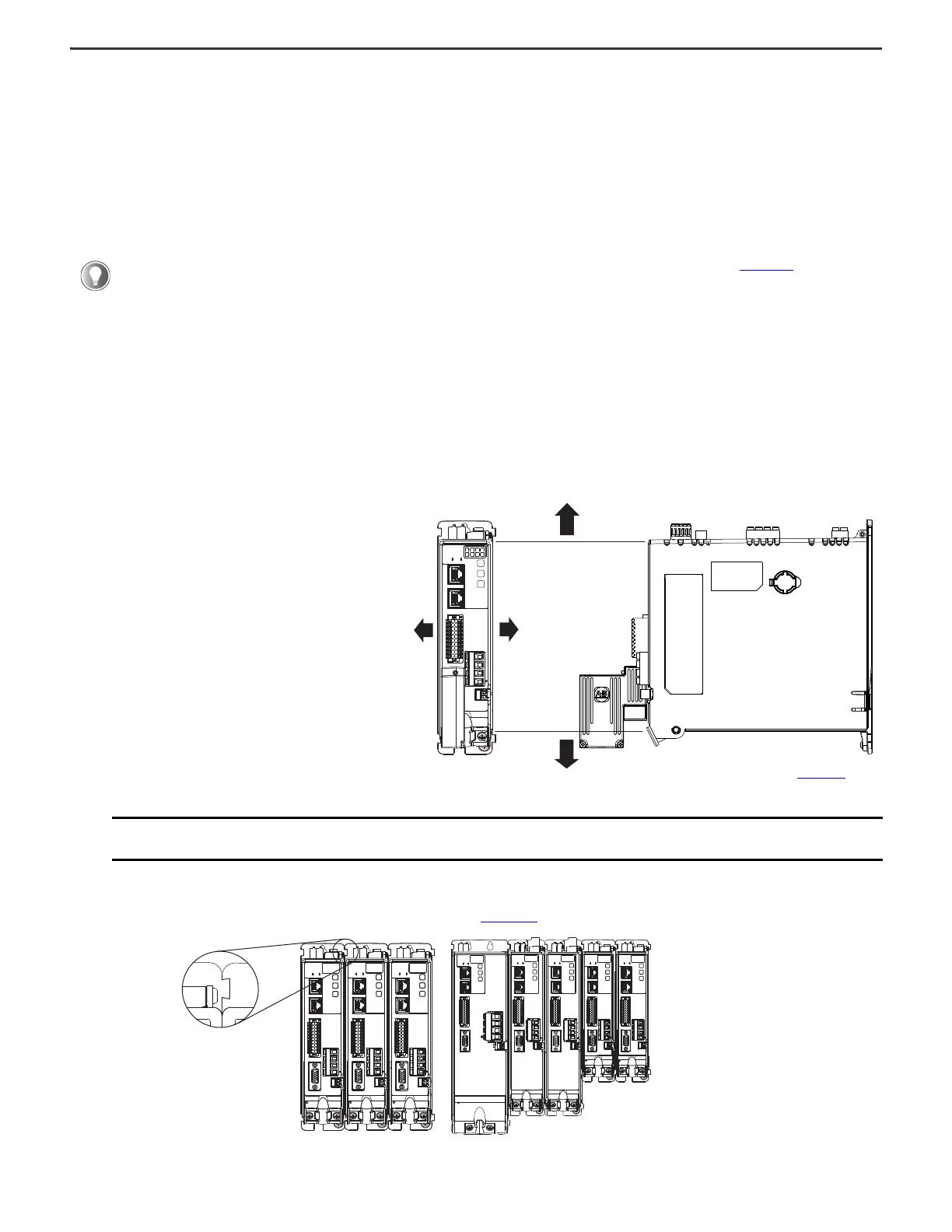
1. Observe these clearance requirements when mounting a single drive to the panel:
• Additional clearance is required for cables and wires connected to the top of the drive.
• Additional clearance is required if other devices are installed above and/or below the drive and have clearance requirements of their own.
• Additional clearance left and right of the drive is required when mounted adjacent to noise sensitive equipment or clean wire ways.
• The recommended minimum cabinet depth is 300 mm (11.81 in.).
Drives can be spaced by aligning the zero-stack tab and cutout. For the zero-stack feature to engage properly (when more than one frame size exists in the drive
system) frame 3 drives must mount left of frame 1 or 2 drives, and frame 2 drives must mount left of frame 1 drives. For additional mounting and 24V shared-bus
information, refer to the Kinetix 5300 Servo Drives User Manual, publication 2198-UM005
.
2. Mount the Kinetix 5300 drive to the cabinet subpanel with M4 (#8-32) steel machine screws torqued to 2.0 N•m (17.7 lb•in) max.
Replacement connector sets are also available. See the Kinetix Servo Drives Specifications Technical Data, publication KNX-TD003, for more
information.
IMPORTANT
Mount the drive in an upright position as shown to provide proper air flow. Do not mount the drive on its side. Mount drives in descending
order, left to right, according to frame size.
Clearance right of the
drive is not required.
Clearance left of the
drive is not required.
Kinetix 5300
Servo Drive
40 mm (1.57 in.) clearance below
drive for airflow
40 mm (1.57 in.) clearance above
drive for airflow
Refer to the Kinetix Servo Drives
Technical Data, publication KNX-TD003
,
for Kinetix 5300 drive dimensions.
MBRK
W
V
U
1
10
1
2
MFB
MBRK
W
V
U
1
10
1
2
MFB
MBRK
W
V
U
1
10
1
2
MFB
Zero-stack Tab and
Cutout Aligned
MBRK
1
10
1
2
MFB
U
V
W
MBRK
W
V
U
1
2
MFB
MBRK
W
V
U
1
10
1
2
MBRK
1
10
1
2
MFB
U
V
W
MBRK
1
10
1
2
MFB
U
V
W
1
10
Mount drives in descending order, left to
right, according to frame size.
The optional 24V shared-bus connection
system is not shown for clarity.
 Loading...