Rockwell Automation Publication 2198-IN021A-EN-P - June 2020 9
Kinetix 5300 Single-axis EtherNet/IP Servo Drives Installation Instructions
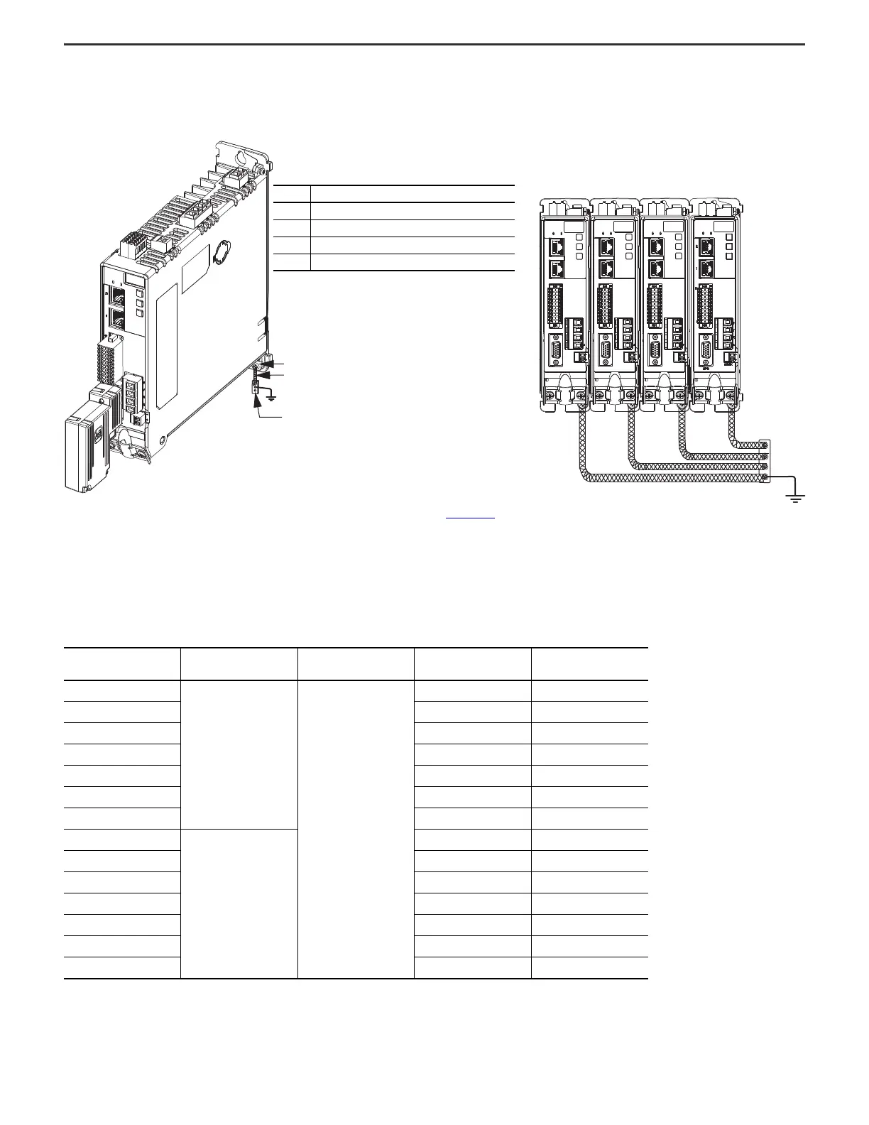
Ground Your Kinetix 5300 Drive to the Subpanel
Ground Kinetix 5300 drives to a bonded cabinet ground bus with a braided ground strap. Keep the braided ground strap as short as possible for optimum bonding.
Connecting the Braided Ground Strap
Refer to the System Design for Control of Electrical Noise Reference Manual, publication GMC-RM001, for more information.
Circuit Breaker/Fuse Selection
The Kinetix 5300 drives use internal solid-state motor short-circuit protection and, when protected by suitable branch circuit protection, are rated for use on a circuit
capable of delivering up to 200,000 A (fuses, UL applications), 10,000 A (miniature circuit breakers), and 65,000 A (molded-case circuit breakers).
Kinetix 5300 UL/CSA Circuit Protection Specifications
Drive Cat. No. AC Input Voltage, nom Phase
Bussmann Fuses
Cat. No.
Molded Case CB
Cat. No.
2198-C1004-ERS
200…240V AC
Three phase
KTK-R-6 140U-D6D3-B40
2198-C1007-ERS KTK-R-10 140U-D6D3-B80
2198-C1015-ERS KTK-R-15 140U-D6D3-C12
2198-C1020-ERS KTK-R-25 140U-D6D3-C20
2198-C2030-ERS KTK-R-30 140U-D6D3-C30
2198-C2055-ERS LPJ-50SP 140G-G6C3-C50
2198-C2075-ERS LPJ-60SP 140G-G6C3-C60
2198-C4004-ERS
380…480V AC
KTK-R-3 140U-D6D3-B20
2198-C4007-ERS KTK-R-6 140U-D6D3-B40
2198-C4015-ERS KTK-R-12 140U-D6D3-B80
2198-C4020-ERS KTK-R-15 140U-D6D3-C12
2198-C4030-ERS KTK-R-25 140U-D6D3-C15
2198-C4055-ERS LPJ-30SP 140U-D6D3-C30
2198-C4075-ERS LPJ-35SP 140U-D6D3-C30
MBRK
W
V
U
1
10
1
2
MFB
MBRK
W
V
U
1
10
1
2
MFB
MBRK
W
V
U
1
10
1
2
MFB
4
3
2
1
Kinetix 5300
Servo Drive
(standalone)
Kinetix 5300
Servo Drives
Item Description
1 Ground screw (green) 2.0 N•m (17.5 lb•in) max
2 Braided ground strap (customer supplied)
3Ground grid or power distribution ground
4 Bonded cabinet ground bus (customer supplied)
 Loading...