EasyManuals Logo

Rockwell Automation Allen-Bradley 1502 User Manual

Rockwell Automation Allen-Bradley 1502
58 pages
To Next Page IconTo Next Page
To Previous Page IconTo Previous Page
Page #43 background imageLoading...
Page #43 background image
4-14 Maintenance
1502-UM051E-EN-P – June 2013
Yellow
Black
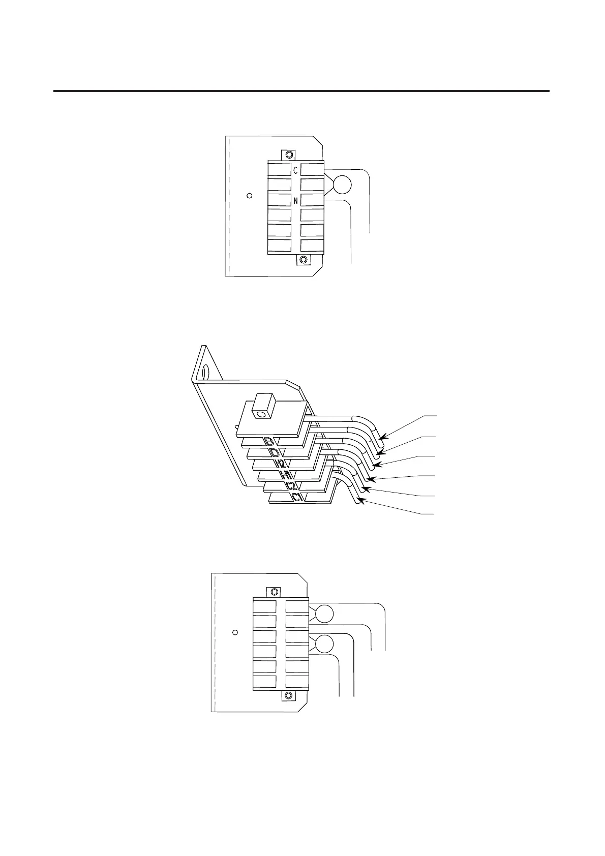
Figure 4.17 – Terminal Block Assembly (Electrically Held Series E Contactor)
Trip Coil (blue lead)
Trip Coil (white lead)
Closing Coil (black lead)
Closing Coil (yellow lead)
Hold-in Coil (blue lead)
Hold-in Coil (yellow lead)
Figure 4.18 – Terminal Block Assembly (Mechanically Latched Series D Contactor)
Yellow
Main Coil
Trip Coil
Black
White
Blue
C
A
D
B
Figure 4.19 – Terminal Block Assembly (Mechanically Latched Series E Contactor)
Main Coil Replacement
Procedure (cont.)

Questions and Answers:

Question and Answer IconNeed help?

Do you have a question about the Rockwell Automation Allen-Bradley 1502 and is the answer not in the manual?

Rockwell Automation Allen-Bradley 1502 Specifications

General IconGeneral
BrandRockwell Automation
ModelAllen-Bradley 1502
CategoryController
LanguageEnglish

Related product manuals