Chapter 5
Troubleshooting
If an operating problem occurs, use the following troubleshooting chart to
isolate the cause of the failure and nd the corrective action. If the corrective
action fails to resolve the problem, consult your local Rockwell Automation eld
support representative.
1502-UM051E-EN-P – June 2013
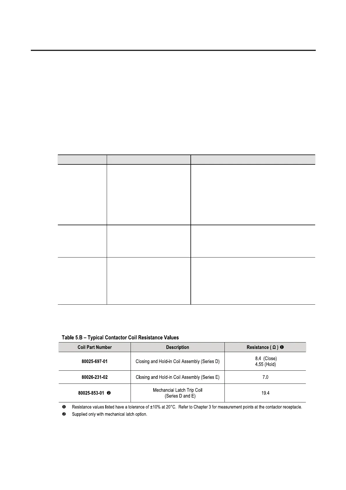
Table 5.A – Troubleshooting (Series D contactors)
Symptom Possible Cause Remedy
Contactor
chatters
5 Loose connections in control circuit
5 Improper control wiring
5 Control voltage
5 Mechanical latch not engaging
5 Improper set-up of auxiliary contact
assembly
5 Faulty auxiliary contacts
5 Faulty CR1 or CR2 interposing relay
5 Check all connections in control circuit for tightness.
Check wiring from the coil to the terminal block assembly.
5 Check wiring per schematic.
5 Measure control voltage. Refer to Contactor Specifications
for minimum pick-up voltage.
5 Check for free movement of latch lever.
5 Check set-up of auxiliary contact assembly.
5 Check master contact cartridges on contactor.
5 Check CR1 and CR2 relay.
Coil burnout
5 Coil leads improperly wired
5 Control voltage too high
5 Contactor operated too frequently
5 Check wiring from the coil to the terminal block assembly.
5 Check for correct control voltage
5 Check switching frequency:
– 600 ops/hr electrically held
– 150 ops/hr mechanically held
Contactor
does not
energize
5 Loose connections in control circuit
5 Improper control wiring
5 Control voltage
5 Improper set-up of auxiliary contact
assembly
5 Faulty CR1 or CR2 interposing relay
5 Check all connections in control circuit for tightness.
Check wiring from the coil to the terminal block assembly.
5 Check wiring per schematic.
5 Measure control voltage. Refer to Contactor Specifications
for pick-up voltage.
5 Check set-up of auxiliary contact assembly.
5 Check CR1 and CR2 relay.
For Series E contactors with IntelliVAC control or IntelliVAC Plus control, refer to Publications 1503-UM053_-EN-P or 1503-UM054_-EN-P
respectively.
 Loading...


