4-22 Maintenance
1502-UM051E-EN-P – June 2013
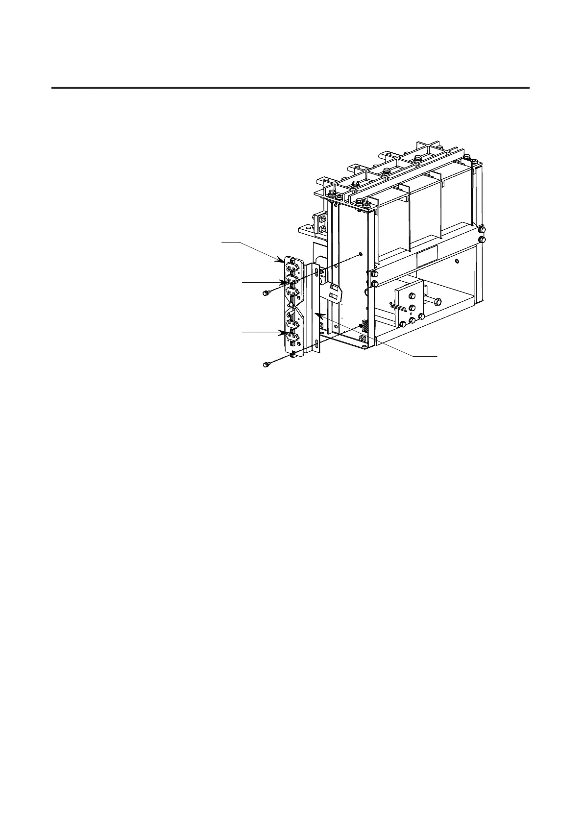
Top cartridges normally closed
(See Note on previous page)
Bottom cartridges normally open
Auxiliary assembly removed
Figure 4.27 – Auxiliary Contact Assembly
1PTJUJPOUIFOFXBTTFNCMZPOUIFMFĕTJEFQMBUFPGUIFDPOUBDUPSXJUIUIF
DBNGPMMPXFSTTFF'JHVSFQSPUSVEJOHUISPVHIUIFSFDUBOHVMBSIPMFTJO
the operating lever. Install and allow the mounting bolts to remain loose so
that the assembly can slide vertically on its mounting slots.
8JUIUIFDPOUBDUPSiPĈ uQVTIUIFFOUJSFBVYJMJBSZBTTFNCMZVQVOUJMUIFDBN
followers bottom out against the top of the rectangular holes in the operat-
JOHMFWFSBTTIPXOJO'JHVSFNBLFTVSFUIFBSNBUVSFQMBUFJTBHBJOTU
UIFTUPQTVDIUIBUUIFDPOUBDUPSJTGVMMZPQFO"UUIJTQPJOUUIFUPQTFUPG
BVYJMJBSZDPOUBDUTBSFiDMPTFEuBOEUIFCPUUPNTFUPGBVYJMJBSZDPOUBDUTBSF
iPQFOu
5JHIUFOBOEUPSRVFĕMCUIFNPVOUJOHCPMUTUPđYUIFQPTJUJPOPGUIF
BVYJMJBSZBTTFNCMZ
Auxiliary Contact Replacement
and Set-Up Procedure (cont.)
 Loading...


