36 Rockwell Automation Publication ENET-IN002H-EN-P - August 2017
Chapter 3 Install a 1769 EtherNet/IP Adapter
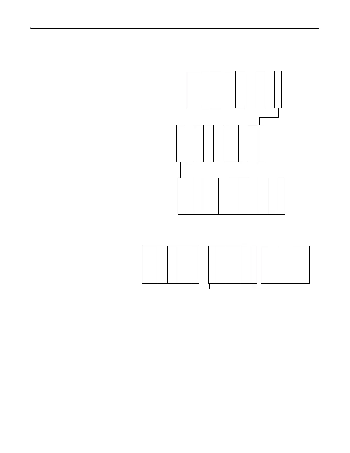
Example Configurations
The following illustrations show examples of two valid system setups.
I/O modules are not required between either the adapter and an end cap
or between the power supply and an end cap.
Bank 1
Bank 2
Bank 3
Bank 3Bank 2Bank 1
Right-to-Right Cable
1769-AENTR
1769 I/O
1769 I/O
1769-CRRx
I/O Slot Number
12
I/O Slot Number
10 11 12
1769-CLLx
1769 I/O
1769 I/O
1769 I/O
1769-CRRx
1769 Power Supply
1769-CLLx
1769 I/O
1769 I/O
1769 I/O
1769 I/O
1769 Right End Cap
I/O Slot Number
20
1769 I/O
1769-CRLx
1769-CRLx
1769 I/O
1769 I/O
1769-CRLx
1769 Power Supply
1769-CRLx
1769 I/O
1769 Power Supply
1769 I/O
1769 Right End Cap
I/O Slot Number
12 3 4 5 6
Left-to-Left Cable
42131
1769 I/O
1769 I/O
1769 Power Supply
34 5
1769 I/O
1769 I/O
6
1769 I/O
1769 Power Supply
1769 I/O
1769 I/O
987
1769 I/O
1769 I/O
1769 I/O
1769 I/O
19181716151413
1769-AENTR
1769 I/O
1769 Power Supply
Right-to-Left Cable Right-to-Left Cable
 Loading...


