Rockwell Automation Publication 1769-IN088A-EN-P - February 2011 131
I/O Memory Mapping Chapter 3
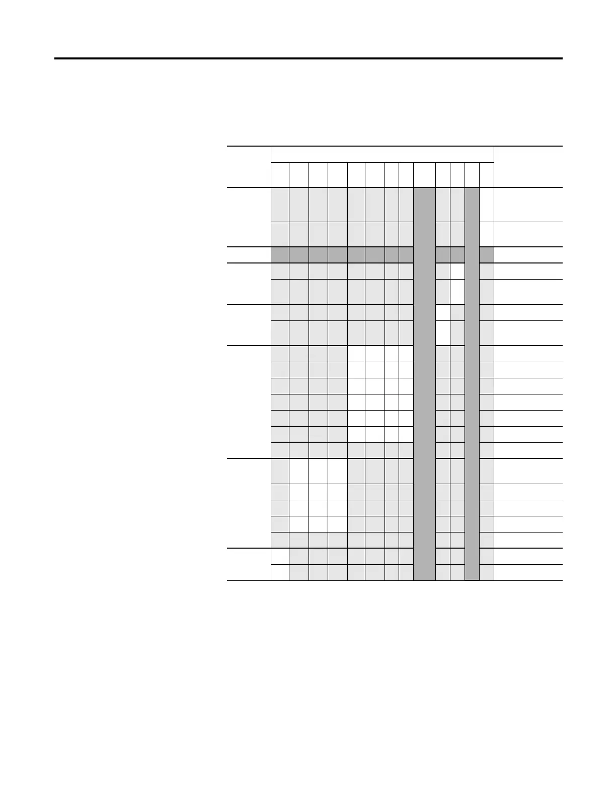
Channel Configuration Words
Words 0 and 1 of the configuration file allow you to change the parameters of
each channel independently. For example, word 0 corresponds to channel 0.
Define These bit settings Indicate this
15 14 13 12 11 10 9 8 4…
7
3210
Program
(Idle) to
Fault
Enable
Not Used
Not Used
0 Program (Idle)
Mode Data
Applied
(1)
(1) These functions are not supported by all controllers, such as MicroLogix 1500, using any configuration method.
Refer to your controller manual for details.
1 Fault Mode Data
Applied
(1)
Not Used (Reserved)
Program
(Idle)
Mode
0 Hold Last State
(1)
1 User-Defined
Value
(1)
Fault
Mode
0 Hold Last State
(1)
1 User-Defined
Fault Value
(1)
Output
Range
Select
00 00 -10V dc to +10V dc
00 01 0 to 5V dc
00 10 0 to 10V dc
00 11 4 to 20 mA
01 00 1 to 5V dc
01 01 0 to 20 mA
Spare
(2)
(2) Any attempt to write a nonvalid (spare) bit configuration into any selection field results in a module
configuration error.
Output
Data
Select
000 Raw/Proportional
Data
001 Engineering Units
010 Scaled-for-PID
011 Percent Range
Spare
(2)
Enable
Channel
1 Enabled
0
Disabled
 Loading...


