Rockwell Automation Publication 1769-IN088A-EN-P - February 2011 163
I/O Memory Mapping Chapter 3
Configuration File
The read/writable configuration data file allows the setup of the hold last state
and user-defined safe state conditions.
The manipulation of the bits from this file is normally done with programming
software, such as RSLogix 500, RSLogix 5000, or RSNetWorx for DeviceNet,
during initial configuration of the system. In that case, graphical dialogs are
provided via the programmer to simplify configuration. However, some systems,
like the 1769-ADN DeviceNet adapter, also allow the bits to be altered as part of
the control program using communication rungs. In that case, it is necessary to
understand the bit arrangement.
Program State Word
Word 1, the program state word, selects the hold last state or user-defined safe
state condition for each individual output on a system transition from Run to
Program.
Program Value Word
(1)
The program value word, word 2, is used to program the user-defined safe state
value (0 = Off, 1 = On). Each output is individually configurable for on or off.
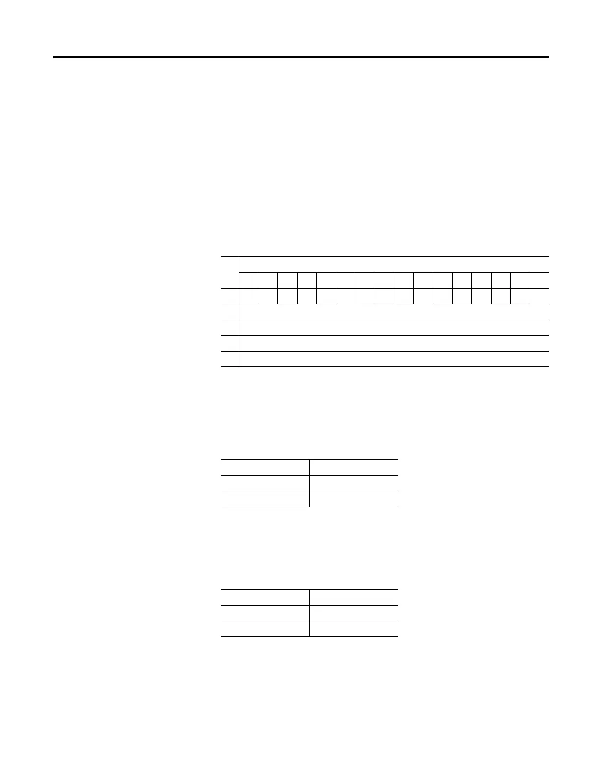
Word
Bit Position
1514131211109876543210
0000000000000000PFE
1 Program State for Output Array Word 0
2 Program Value for Output Array Word 0
3 Fault State for Output Array Word 0
4 Fault Value for Output Array Word 0
Condition Bit Setting
User-defined Safe State 0
Hold Last State 1
(1) TTL outputs are inverted (On = 1 = logic low voltage = 0…0.4V dc; Off = 0 = logic high voltage = 4.5…5.5V dc).
Use a NOT instruction in the ladder program to convert to traditional True = High logic.
Value Bit Setting
Off 0
On 1
 Loading...


