132 Rockwell Automation Publication 1769-IN088A-EN-P - February 2011
Chapter 3 I/O Memory Mapping
1769-OF4
The following I/O memory mapping lets you configure the 1769-OF4 module.
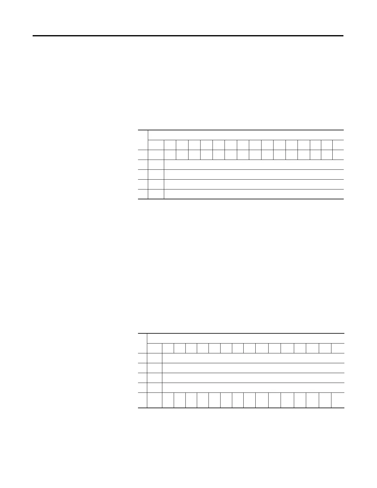
Input Data File
For each module, slot x, word 0 in the input data file contains the status bits for
the module’s analog output channels. Words 1…4 contain the directed values of
the analog output channels (output data echo).
The bits are defined as follows:
• SGN = Sign bit in 2’s complement format.
• NU = Not Used. Bit must be set to 0.
• Sx = General Status bit for output channels 0…3.
• Ox = Over range flag bits for output channels 0…3.
• Ux = Under range flag bits for output channels 0…3.
Output Data File
For each module, slot x, words 0…3 in the output data file contain the control
program’s directed state of the module’s analog output channels. Word 4 contains
the cancel output-channel-clamp alarm control bits.
Word
Bit Position
15 14 13 12 11 10 09 08 07 06 05 04 03 02 01 00
0U3 O3U2O2U1O1U0O0NUNUNUNUS3S2S1S0
1 SGN Output Data Loopback/Echo Channel 0
2 SGN Output Data Loopback/Echo Channel 1
3 SGN Output Data Loopback/Echo Channel 2
4 SGN Output Data Loopback/Echo Channel 3
Word
Bit Position
15 14 13 12 11 10 09 08 07 06 05 04 03 02 01 00
0 SGN Analog Output Data Channel 0
1 SGN Analog Output Data Channel 1
2 SGN Analog Output Data Channel 2
3 SGN Analog Output Data Channel 3
4 NU NUNUNUNUNUNUNUCLO
3
CHO
3
CLO
2
CHO
2
CLO
1
CHO
1
CLO
0
CHO
0
 Loading...


