162 Rockwell Automation Publication 1769-IN088A-EN-P - February 2011
Chapter 3 I/O Memory Mapping
1769-OG16
The following I/O memory mapping lets you configure the 1769-OG16 module.
Output Module’s Input Data File
For each module, slot x, word 0 in the input data file contains the state of the
module’s output data file (output data echo). During normal operation, these
input bits represent the logic state that the outputs are directed to by the control
program. They are also dependent upon these configurations:
• Program mode configuration, if supported by the controller
• Fault mode configuration, if supported by the controller
The module implements inverted logic on the TTL outputs. An Output Data
File bit set to 1 directs a logic low output voltage on the corresponding output
point. An Output Data File bit cleared to 0 directs a logic high output voltage on
the corresponding output point.
Output Data File
For each module, slot x, word 0 in the output data file contains the state of the
module’s output points. The module implements inverted logic on the TTL
outputs. An Output Data File bit set to 1 results in a logic low output voltage on
the corresponding output point. An Output Data File bit cleared to 0 results in a
logic high output voltage on the corresponding output point.
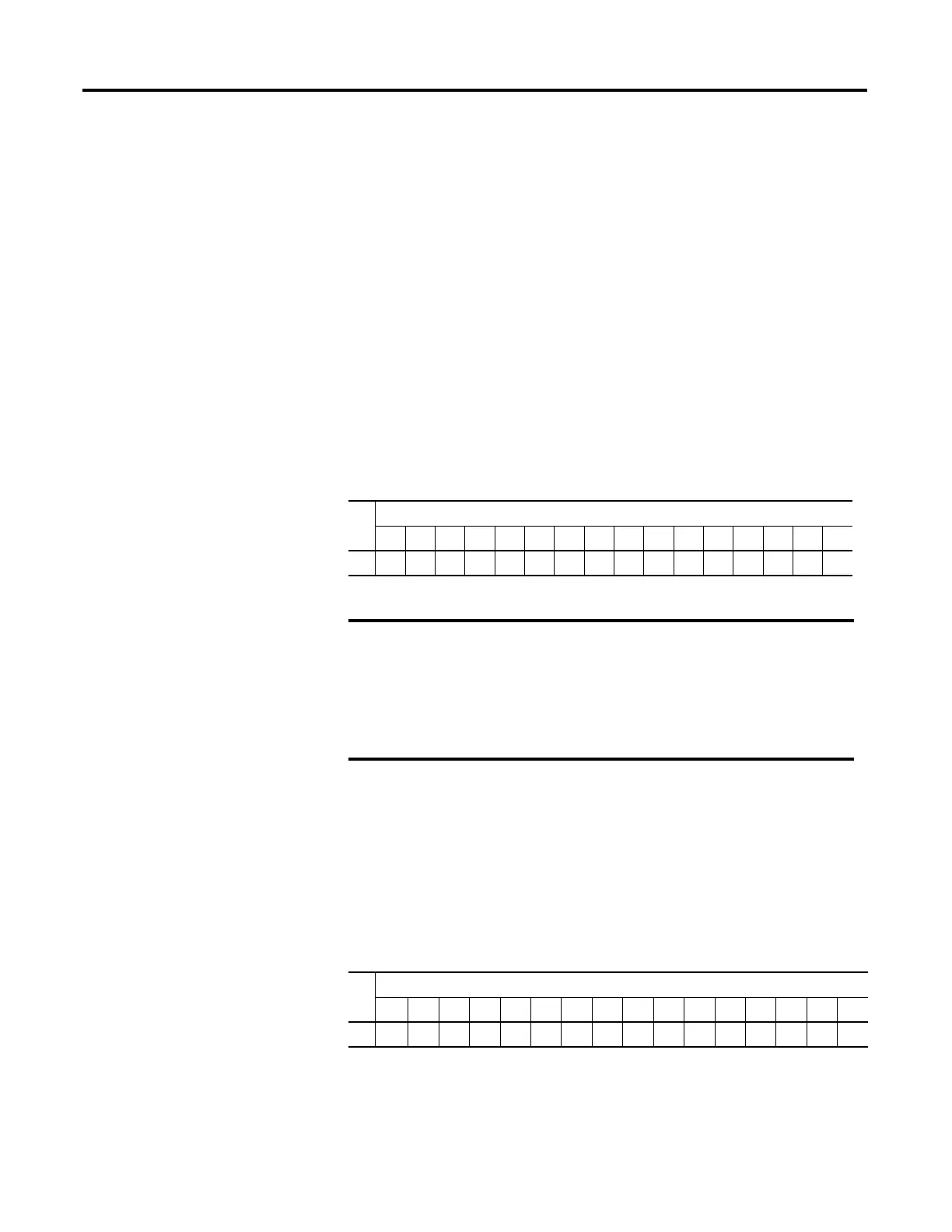
Word
Bit Position
1514131211109876543210
0r
(1)
(1) r = read.
rrrrrrrrrrrrrrr
The output module’s input data file reflects the output data echo of the
module, not necessarily the electrical state of the output terminals. It
does not reflect shorted or open outputs.
It is important to use this input word if the controller adapter supports
the Program mode or Fault mode function, and if it is configured to use
them.
Word
Bit Position
1514131211109876543210
0w
(1)
(1) w = write.
wwwwwwwwwwwwwww
 Loading...


